Nissan Juke Service and Repair Manual : Main power supply and ground circuit
Diagnosis Procedure
1.CHECK TCM POWER CIRCUIT 1
1. Turn the ignition switch OFF.
2. Disconnect the TCM connector.
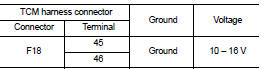
3. Check the voltage between the TCM harness connector terminals and ground.
Is the inspection result normal? YES >> GO TO 2.
NO >> GO TO 4.
2.CHECK TCM POWER CIRCUIT 2
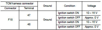
Check the voltage between the TCM harness connector terminals and ground.
Is the inspection result normal? YES >> GO TO 3.
NO >> GO TO 5.
3.CHECK TCM GROUND CIRCUIT
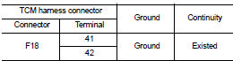
Check the continuity between TCM harness connector terminals and ground.
Is the inspection result normal? YES >> Check intermittent incident. Refer to GI-42, "Intermittent Incident".
NO >> Repair or replace the malfunctioning parts.
4.DETECT MALFUNCTION ITEMS (PART 1)
Check the following items: • Open or short circuit of the harness between battery positive terminal and TCM connectors terminals 45 and 46. Refer to PG-10, "Wiring Diagram - BATTERY POWER SUPPLY -".
• 10A fuse (No.33, fuse and fusible link block). Refer to PG-23, "Fuse and Fusible Link Arrangement".
• 10A fuse (No.36, fuse and fusible link block). Refer to PG-23, "Fuse and Fusible Link Arrangement".
Is the inspection result normal? YES >> Check intermittent incident. Refer to GI-42, "Intermittent Incident".
NO >> Repair or replace the malfunctioning parts.
5.CHECK CIRCUIT BETWEEN IPDM E/R AND TCM (PART 1)
1. Turn ignition switch OFF.
2. Disconnect the IPDM E/R connector.
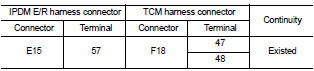
3. Check continuity between IPDM E/R harness connector terminal and TCM harness connector terminals.
Is the check result normal? YES >> GO TO 6.
NO >> Repair or replace the malfunctioning parts.
6.CHECK CIRCUIT BETWEEN IPDM E/R AND TCM (PART 2)
Check continuity between IPDM E/R harness connector terminal and ground.
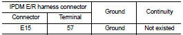
Is the check result normal? YES >> GO TO 7.
NO >> Repair or replace the malfunctioning parts.
7.DETECTION OF MALFUNCTION ITEMS (PART 2)
Check the following items: • Harness open circuit or short circuit between the ignition switch and IPDM E/R. Refer to PG-15, "Wiring Diagram - IGNITION POWER SUPPLY -".
• 10A fuse (No.55, IPDM E/R). Refer to PG-25, "Fuse, Connector and Terminal Arrangement".
• IPDM E/R
Is the check result normal? YES >> Check intermittent incident. Refer to GI-42, "Intermittent Incident".
NO >> Repair or replace the malfunctioning parts.
 P2765 clutch B speed sensor
DTC Logic
DTC DETECTION LOGIC
DTC CONFIRMATION PROCEDURE
CAUTION:
Be careful of the driving speed.
1.PREPARATION BEFORE WORK
If another "DTC CONFIRMATION PROCEDURE" occurs just befor ...
 S mode switch
Component Function Check
1.CHECK S MODE INDICATOR FUNCTION
Check S mode indicator turns ON for approx. 2 seconds when ignition switch
turns ON.
Is the inspection results normal?
YES >> G ...
Other materials:
Disposal of air bag module
Driver air bag module : Deployment
CHECKING DEPLOYMENT TOOL
Connecting to Battery
CAUTION:
The battery must show voltage of 9.6 V or more.
Remove the battery from the vehicle and place it on dry wood blocks
approximately 5.0 m (16.4 ft) away from the vehicle.
• Wait 3 minutes after the ve ...
Drive belt
Checking Drive Belts
WARNING:
Be sure to perform when the engine is stopped.
1. Inspect belts for cracks, fraying, wear and oil. If necessary,
replace.
2. Evaluate manually if the belt is enough tensioned (tension cannot
be measured by way of frequency meter).
CAUTION:
Auto-tensioner must ...
B26F0 steering lock relay
DTC Logic
DTC DETECTION LOGIC
NOTE:
• If DTC B26F0 is displayed with DTC U1000, first perform the trouble diagnosis
for DTC U1000. Refer to
BCS-83, "DTC Logic".
• If DTC B26F0 is displayed with DTC U1010, first perform the trouble diagnosis
for DTC U1010. Refer to
BCS-84, &qu ...
