
Nissan Juke Service and Repair Manual : A/C auto AMP. Connection recognition signal circuit
Diagnosis Procedure
1.CHECK A/C AUTO AMP. CONNECTION RECOGNITION SIGNAL
1. Turn ignition switch ON.
2. Check voltage between combination meter harness connector and ground.
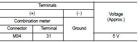
Is the inspection result normal? YES >> INSPECTION END
NO >> GO TO 2.
2.CHECK A/C AUTO AMP. CONNECTION RECOGNITION SIGNAL CIRCUIT
1. Turn ignition switch OFF.
2. Disconnect combination meter connector and A/C auto amp. connector.
3. Check continuity between combination meter harness connector and A/C auto amp. harness connector.

*1: 4WD models
*2: 2WD models
4. Check continuity between combination meter harness connector and ground.

Is the inspection result normal? YES >> INSPECTION END
NO >> Repair harness or connector.
 Seat belt buckle switch signal circuit (passenger side)
Diagnosis Procedure
1.CHECK SEAT BELT BUCKLE SWITCH (PASSENGER SIDE) CIRCUIT
1. Turn ignition switch OFF.
2. Disconnect combination meter connector and seat belt buckle switch (passenger
side) co ...
 PTC heater control unit connection recognition signal
circuit
PTC heater control unit connection recognition signal
circuit
Diagnosis Procedure
1.CHECK PTC HEATER CONTROL UNIT CONNECTION RECOGNITION SIGNAL
1. Turn ignition switch ON.
2. Check voltage between combination meter harness connector and ground.
Is the insp ...
Other materials:
Precaution for Harness Repair
• Solder the repair part, and wrap it with tape. [Twisted wire fray
must be 110 mm (4.33 in) or less.]
• Never bypass the repair point with wire. (If it is bypassed, the turnout
point cannot be separated and the twisted wire characteristics
are lost.)
...
Precaution Necessary for Steering Wheel Rotation after Battery Disconnect
NOTE:
• Before removing and installing any control units, first turn the ignition
switch to the LOCK position, then disconnect
both battery cables.
• After finishing work, confirm that all control unit connectors are connected
properly, then re-connect both
battery cables.
• Always us ...
P1197 out of gas
Description
This diagnosis result is detected when the fuel level of the fuel tank is
extremely low and the engine does not
run normally.
DTC Logic
DTC DETECTION LOGIC
DTC CONFIRMATION PROCEDURE
1.PRECONDITIONING
1. Turn ignition switch OFF and wait at least 10 seconds.
2. Turn ignition ...
