Nissan Juke Service and Repair Manual : PTC heater control unit connection recognition signal circuit
Diagnosis Procedure
1.CHECK PTC HEATER CONTROL UNIT CONNECTION RECOGNITION SIGNAL
1. Turn ignition switch ON.
2. Check voltage between combination meter harness connector and ground.
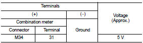
Is the inspection result normal? YES >> INSPECTION END NO >> GO TO 2.
2.CHECK PTC HEATER CONTROL UNIT CONNECTION RECOGNITION SIGNAL CIRCUIT
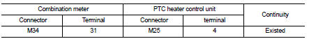
1. Turn ignition switch OFF.
2. Disconnect combination meter connector and PTC heater control unit connector.
3. Check continuity between combination meter harness connector and PTC heater control unit harness connector.
4. Check continuity between combination meter harness connector and ground.
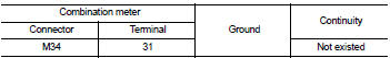
Is the inspection result normal? YES >> INSPECTION END
NO >> Repair harness or connector.
 A/C auto AMP. Connection recognition signal circuit
Diagnosis Procedure
1.CHECK A/C AUTO AMP. CONNECTION RECOGNITION SIGNAL
1. Turn ignition switch ON.
2. Check voltage between combination meter harness connector and ground.
Is the inspection res ...

Other materials:
P1553 battery current sensor
DTC Logic
DTC DETECTION LOGIC
DTC CONFIRMATION PROCEDURE
1.PRECONDITIONING
If DTC Confirmation Procedure has been previously conducted, always perform
the following before conducting
the next test.
1. Turn ignition switch OFF and wait at least 10 seconds.
2. Turn ignition switch ON.
3. ...
Cockpit
TRIP RESET switch for twin trip odometer
Instrument brightness control switch
Headlight, fog light (if so equipped), and turn signal switch
Steering-wheel-mounted controls (left side):
Audio control system*
Vehi ...
Diagnosis system (BCM) (with intelligent key system)
Common item
COMMON ITEM : CONSULT-III Function (BCM - COMMON ITEM)
APPLICATION ITEM
CONSULT-III performs the following functions via CAN communication with BCM.
SYSTEM APPLICATION
BCM can perform the following functions for each system.
NOTE:
It can perform the diagnosis modes except the ...
