Nissan Juke Service and Repair Manual : Oil pressure switch signal circuit
Component Function Check
1.CHECK COMBINATION METER INPUT SIGNAL
Select the ÔÇťData MonitorÔÇŁ for the ÔÇťMETER/M&AÔÇŁ and check the ÔÇťOIL W/LÔÇŁ monitor value.
ÔÇťOIL W/LÔÇŁ
Ignition switch ON : On
Engine running : Off
>> INSPECTION END
Diagnosis Procedure
1.CHECK OIL PRESSURE SWITCH CIRCUIT
1. Turn ignition switch OFF.
2. Disconnect IPDM E/R connector and oil pressure switch connector.
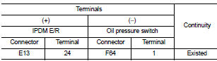
3. Check continuity between IPDM E/R harness connector and oil pressure switch harness connector.
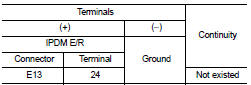
4. Check continuity between IPDM E/R harness connector and ground.
Is the inspection result normal? YES >> INSPECTION END
NO >> Repair harness or connector.
Component Inspection
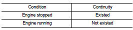
1.CHECK OIL PRESSURE SWITCH
Check continuity between oil pressure switch and ground.
Is the inspection result normal? YES >> INSPECTION END
NO >> Replace oil pressure switch. Refer to LU-8, "Inspection" (MR16DDT), LU-25, "Inspection" (HR16DE), or LU-33, "Inspection" (K9K).
 Fuel level sensor signal circuit
Component Function Check
2WD MODELS
1.CHECK COMBINATION METER OUTPUT SIGNAL
Select the ÔÇťData MonitorÔÇŁ for the ÔÇťMETER/M&AÔÇŁ and compare the ÔÇťFUEL METERÔÇŁ
monitor value with the fuel
...
 Seat belt buckle switch signal circuit (driver side)
Component Function Check
1.CHECK COMBINATION METER INPUT SIGNAL
Select the ÔÇťData MonitorÔÇŁ for the ÔÇťMETER/M&AÔÇŁ and check the ÔÇťBUCKLE SWÔÇŁ
monitor value.
BUCKLE SW
When driver seat ...
Other materials:
Check anti-pinch function
Description
If any of the following operations are performed, the initialization is
necessary for normal operation of antipinch
function.
ÔÇó Disconnection and connection of battery cable from negative terminal.
ÔÇó When power window main switch replaced.
ÔÇó Electric power supply to power ...
Wiring diagram
BCM
LHD
LHD : Wiring Diagram
For connector terminal arrangements, harness layouts, and alphabets in a
(option abbreviation; if not
described in wiring diagram), refer to GI-12, "Connector Information/Explanation
of Option Abbreviation".
RHD
RHD : Wiring Diagram
For con ...
C1110 ABS actuator and electric unit (control unit)
DTC Logic
DTC DETECTION LOGIC
DTC CONFIRMATION PROCEDURE
1.PRECONDITIONING
If ÔÇťDTC CONFIRMATION PROCEDUREÔÇŁ has been previously conducted, always turn
ignition switch OFF and
wait at least 10 seconds before conducting the next test.
>> GO TO 2.
2.CHECK DTC DETECTION
With CON ...
