Nissan Juke Service and Repair Manual : Wiring diagram
BCM
LHD
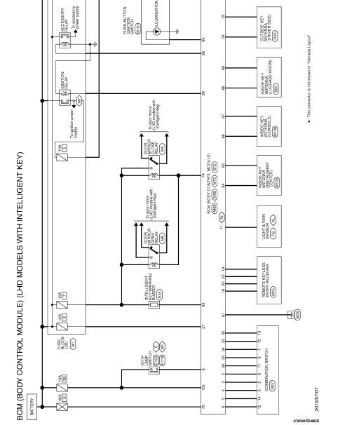
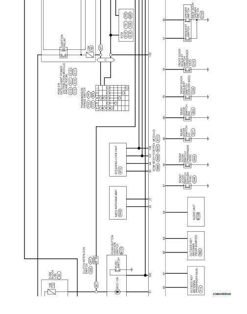
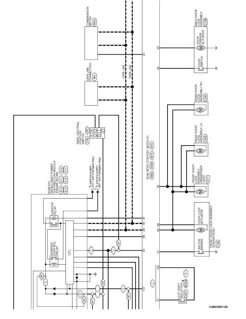
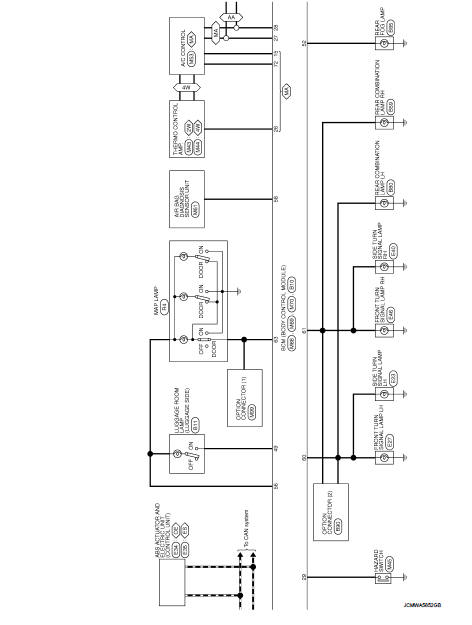
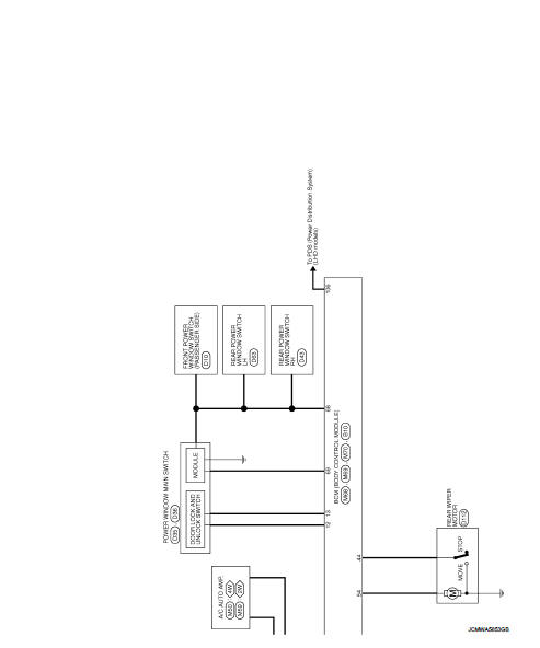
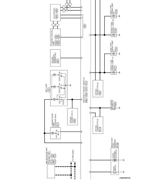
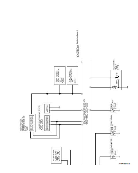
LHD : Wiring Diagram
For connector terminal arrangements, harness layouts, and alphabets in a
 (option abbreviation; if not
described in wiring diagram), refer to GI-12, "Connector Information/Explanation
of Option Abbreviation".
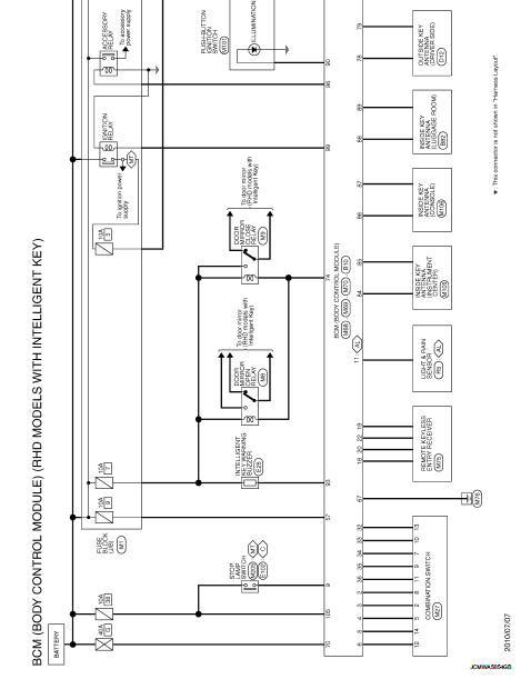
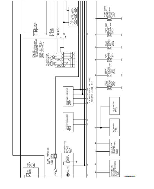
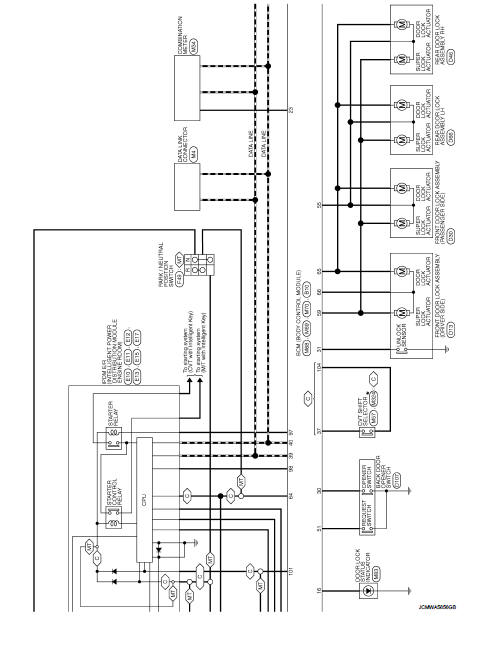
RHD
RHD : Wiring Diagram
For connector terminal arrangements, harness layouts, and alphabets in a
 (option abbreviation; if not
described in wiring diagram), refer to GI-12, "Connector Information/Explanation
of Option Abbreviation".
 Ecu diagnosis information
BCM
Reference Value
VALUES ON THE DIAGNOSIS TOOL
CONSULT-III MONITOR ITEM
TERMINAL LAYOUT
PHYSICAL VALUES
• *1: With manual A/C
• *2: RHD mod ...
 Basic inspection
Inspection and adjustment
Additional service when replacing control unit (BCM)
ADDITIONAL SERVICE WHEN REPLACING CONTROL UNIT (BCM) : Description
BEFORE REPLACEMENT
When replacing BCM, save or pri ...
Other materials:
On board diagnostic (OBD) system
Description
This is an onboard diagnosis system which records diagnosis information
related to the exhaust gases. It
detects malfunctions related to sensors and actuators. The malfunctions are
indicated by means of the malfunction
indicator lamp (MIL) and are stored as DTC in the ECU memory. ...
Cylinder head
Exploded View
REMOVAL
1. Cylinder head assembly
2. Cylinder head bolt
3. Cylinder head gasket
A. Tightening must be done following
the installation procedure.
Refer to EM-91
: N·m (kg-m, ft-lb)
: Always replace after every
disassembly.
: Should be lubricated with oil.
DISASSEMBLY ...
Diagnosis system (BCM) (without intelligent key system)
common item
Common item : consult-III Function (BCM - common item)
APPLICATION ITEM
CONSULT-III performs the following functions via CAN communication with BCM.
SYSTEM APPLICATION
BCM can perform the following functions for each system.
NOTE:
It can perform the diagnosis modes except the following for ...
