Nissan Juke Service and Repair Manual : Basic inspection
Inspection and adjustment
Additional service when replacing control unit (BCM
)
ADDITIONAL SERVICE WHEN REPLACING CONTROL UNIT (BCM) : Description
BEFORE REPLACEMENT
When replacing BCM, save or print current vehicle specification with CONSULT-III configuration before replacement.
NOTE
:
If ÔÇťREAD CONFIGURATIONÔÇŁ can not be used, use the ÔÇťWRITE CONFIGURATION - Manual
selectionÔÇŁ after
replacing BCM.
AFTER REPLACEMENT
CAUTION:
ÔÇó When replacing BCM, you must perform ÔÇťWRITE CONFIGURATIONÔÇŁ with CONSULT-III.
- Complete the procedure of ÔÇťWRITE CONFIGURATIONÔÇŁ in order.
- If you set incorrect ÔÇťWRITE CONFIGURATIONÔÇŁ, incidents might occur.
- Configuration is different for each vehicle model. Confirm configuration of each vehicle model.
ÔÇó When replacing BCM, perform the system initialization (NATS).
ADDITIONAL SERVICE WHEN REPLACING CONTROL UNIT (BCM) : Special Repair Requirement
1.SAVING VEHICLE SPECIFICATION
 CONSULT-III Configuration
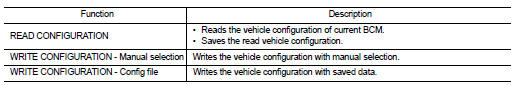
Perform ÔÇťREAD CONFIGURATIONÔÇŁ to save or print current vehicle specification. Refer to BCS-80, "CONFIGURATION (BCM) : Description".
NOTE
:
If ÔÇťREAD CONFIGURATIONÔÇŁ can not be used, use the ÔÇťWRITE CONFIGURATION - Manual
selectionÔÇŁ after
replacing BCM.
>> GO TO 2.
2.REPLACE BCM
Replace BCM. Refer to BCS-93, "Removal and Installation".
>> GO TO 3.
3.WRITING VEHICLE SPECIFICATION
 CONSULT-III Configuration
Perform ÔÇťWRITE CONFIGURATION - Config fileÔÇŁ or ÔÇťWRITE CONFIGURATION - Manual selectionÔÇŁ to write vehicle specification. Refer to BCS-81, "CONFIGURATION (BCM) : Special Repair Requirement".
>> GO TO 4.
4.INITIALIZE BCM (NATS)
Perform BCM initialization. (NATS) >> WORK END
Configuration (BCM)
CONFIGURATION (BCM) : Description
Vehicle specification needs to be written with CONSULT-III because it is not written after replacing BCM.
Configuration has three functions as follows
CAUTION:
ÔÇó When replacing BCM, you must perform ÔÇťWRITE CONFIGURATIONÔÇŁ with CONSULT-III.
ÔÇó Complete the procedure of ÔÇťWRITE CONFIGURATIONÔÇŁ in order.
ÔÇó If you set incorrect ÔÇťWRITE CONFIGURATIONÔÇŁ, incidents might occur.
ÔÇó Configuration is different for each vehicle model. Confirm configuration of each vehicle model.
ÔÇó Never perform ÔÇťWRITE CONFIGURATIONÔÇŁ except for new BCM.
CONFIGURATION (BCM) : Special Repair Requirement
1.WRITING MODE SELECTION
 CONSULT-III Configuration
Select ÔÇťCONFIGURATIONÔÇŁ of BCM.
When writing saved data>>GO TO 2.
When writing manually>>GO TO 3.
2.PERFORM ÔÇťWRITE CONFIGURATION - CONFIG FILEÔÇŁ
 CONSULT-III Configuration
Perform ÔÇťWRITE CONFIGURATION - Config fileÔÇŁ.
>> WORK END 3.PERFORM ÔÇťWRITE CONFIGURATION - MANUAL SELECTIONÔÇŁ
 CONSULT-III Configuration
1. Select "WRITE CONFIGURATION - Manual selection".
2. Identify the correct model and configuration list. Refer to BCS-81, "CONFIGURATION (BCM) : Configuration list".
3. Confirm and/or change setting value for each item.
CAUTION:
Thoroughly read and understand the vehicle specification. Incorrect settings may
result in abnormal
control of ECU.
4. Select "SETTING".
CAUTION:
Make sure to select ÔÇťSETTINGÔÇŁ even if the indicated configuration of brand new
BCM is same as
the desirable configuration. If not, configuration which is set automatically by
selecting vehicle
model can not be memorized.
5. When "COMMAND FINISHED", select "END".
>> GO TO 4.
4.OPERATION CHECK
Confirm that each function controlled by BCM operates normally.
>> WORK END
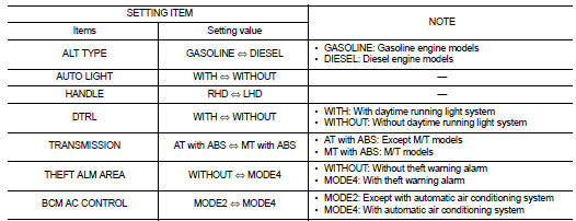
CONFIGURATION (BCM) : Configuration list
CAUTION:
Thoroughly read and understand the vehicle specification. Incorrect settings may
result in abnormal
control of ECU.
2WD MODELS
⇔: Items which confirm vehicle specifications 4WD MODELS
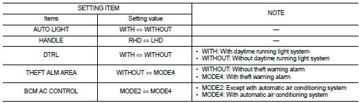
⇔: Items which confirm vehicle specifications
 Wiring diagram
BCM
LHD
LHD : Wiring Diagram
For connector terminal arrangements, harness layouts, and alphabets in a
(option abbreviation; if not
described in wiring diagram), refer to GI-12, "Connector I ...

Other materials:
I-LI system operation
Lane Departure Warning (LDW) indicator icon.
Intelligent Lane Intervention (I-LI) status indicator.
ProPILOT Assist control switch (for Nissan Leaf models equipped with advanced driver assistance).
Dynamic driver assistance master switch (fo ...
Diagnosis system (BCM) (with intelligent key system)
Description
Air conditioning system performs self-diagnosis, operation check, function
diagnosis, and various settings
using diagnosis function of each control unit.
Common item : consult-III Function (BCM - COMMON ITEM)
APPLICATION ITEM
CONSULT-III performs the following functions via CAN ...
Engine idle speed too high
Description
CHART 5: ENGINE IDLE SPEED TOO HIGH
Diagnosis Procedure
1.CHECK ECM POWER SUPPLY AND GROUND CIRCUIT
Check ECM power supply and ground circuit. Refer to EC-885, "Diagnosis
Procedure".
Is the inspection result normal?
YES >> GO TO 2.
NO >> Repair or repla ...
