Nissan Juke Service and Repair Manual : Fuel level sensor unit, fuel filter and fuel pump assembly
Exploded View
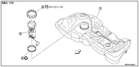
1. Fuel tank
2. Rock ring
3.
Fuel level sensor unit, fuel filter and
fuel pump assembly
4. O-ring
 : Vehicle front
 : Always replace after every
disassembly.
 : N·m (kg-m, ft-lb)
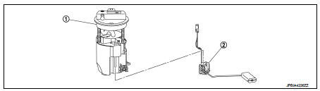
1. Fuel filter and fuel pump assembly 2. Fuel gauge
Removal and Installation
WARNING:
Read “General Precautions” when working on the fuel system. Refer to FL-30,
"General Precautions".
REMOVAL
1. Release the fuel pressure from the fuel lines. Refer to EC-551, "Work Procedure".
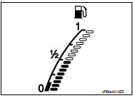
2. Check fuel level on fuel gauge. If fuel gauge indicates more than the level as shown in the figure (full or almost full), drain fuel from fuel tank until fuel gauge indicates level as shown in the figure or below.
NOTE
:
Because fuel will be spilled when removing fuel level sensor units for the top of the fuel is above the fuel level sensor units installation surface.
• As a guide, fuel level becomes the position as shown in the figure or below when approximately 25 (6-5/8 US gal, 5-4/8 Imp gal) of fuel are drained from fuel tank.
• In a case that fuel pump does not operate, perform the following procedure.
a. Insert hose of less than 25 mm (0.98 in) in diameter into fuel filler tube through fuel filler opening to draw fuel from fuel filler tube.
b. Disconnect fuel filler hose from fuel filler tube. Refer to FL-38, "Exploded View".
c. Insert hose into fuel tank through fuel filler hose to draw fuel from fuel tank.
3. Open fuel filler lid.
4. Open filler cap and release the pressure inside fuel tank.
5. Remove rear seat. Refer to SE-32, "Exploded View" .
6. Remove inspection hole cover.
• Using a screwdriver, remove it by turning clips clockwise by 90 degrees.
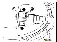
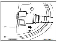
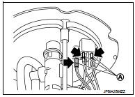
7. Disconnect harness connector (1), fuel feed hose (4) and quick connector (3).
2 : Fuel level sensor unit, fuel filter and fuel pump assembly
 : Vehicle front
• Remove quick connector in the following procedures.
- Pinch quick connector square-part (A) with your fingers, and pull out the quick connector (1) by hand.
- If quick connector and tube on sender unit are stuck, push and pull several times until they move, and pull out.
CAUTION:
• Quick connector can be removed when the tabs are completely
depressed. Never twist it more than necessary.
• Never use any tools to disconnected quick connector.
• Keep resin tube away from heat. Be especially careful when welding near the resin tube.
• Prevent acid liquid such as battery electrolyte, etc. from getting on resin tube.
• Never bend or twist resin tube during installation and disconnection.
• To keep the connecting portion clean and to avoid damage and foreign materials, cover them completely with plastic bags (A) or something similar.
• Never insert plug, preventing damage on O-ring in quick connector.
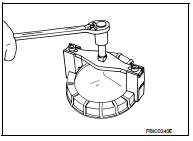
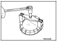
8. Remove lock ring for fuel level sensor unit, fuel filter and fuel pump assembly with fuel tank lock ring wrench [SST: KV99104700] (A) by turning counterclockwise.
INSTALLATION
Note to the following, and install in the reverse order of removal.
Fuel Level Sensor Unit
1. Temporarily install seal packing to the fuel gauge fuel filter fuel pump
assembly.
2. Insert the fuel gauge fuel filter fuel pump assembly into fuel tank and install the above temporarily installed seal packing to the opening of fuel tank.
CAUTION:
Never bend float arm during removal.
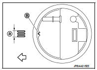
3. Install fuel level sensor unit to fuel tank with alignment mark (B) on the upper surface facing the tree inscribed lines (A) on the tank side.
: Vehicle front
CAUTION:
• Never allow O-ring to drop.
• Never bend float arm during installing.
4. Install lock ring for fuel level sensor unit, fuel filter and fuel pump assembly with lock ring wrench [SST: KV993G0010 or KV99104700] by turning clockwise.
CAUTION:
Install lock ring horizontally.
Quick Connector
Connect quick connector as follows:
1. Check the connection for damage or any foreign materials.
2. Align the connector with the tube, then insert the connector straight into the tube until a click sound is heard.
3. After connecting, check that the connection is secure by following method.
• Visually confirm that the two tabs are connected to the connector.
• Pull (A) the tube and the connector to check they are securely connected.
1 : Quick connector
Disassembly and Assembly
DISASSEMBLY
CAUTION:
Sub fuel level sensor unit cannot be disassembled and should be replaced as a
unit.
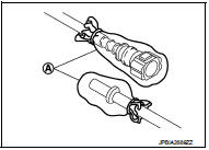
Remove main fuel level sensor unit as follows: 1. Disconnect harness connector (A).
a. Hold connector by fingers and push stopper release tab.
b. Pull it out connector.
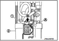
2. Remove main fuel level sensor unit (1) from fuel filter and fuel pump assembly (2) as follows: a. Push in tab (A) to release the lock.
b. After fixing tabs are disengaged, slide main fuel level sensor unit out in direction shown by the arrow (B).
CAUTION:
• Be careful not to damage the main fuel level sensor unit.
• Never disassemble fuel filter and fuel pump assembly.
ASSEMBLY
CAUTION:
Sub fuel level sensor unit cannot be disassembled and should be replaced as a
unit.
1. Check for damage of main fuel level sensor unit installation position on the side of fuel filter and fuel pump assembly.
2. Slide main fuel level sensor unit until it aligns to installation groove, then insert it until it stops.
• After inserting, apply force in reverse direction (removal direction) to ensure it cannot be pulled out.
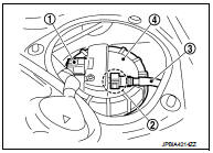
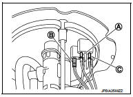
3. Connect the white (A), black (B), and red (C) harnesses so that they are in the positions shown in the figure.
• Securely insert harness connector until it stops.
Inspection
INSPECTION AFTER INSTALLATION
Use the following procedure to check for fuel leakage.
1. Turn ignition switch “ON” (with engine stopped), then check connections for leakage by applying fuel pressure to fuel piping.
2. Start engine and let it idle and check there are no fuel leakage at the fuel system connections.

 Fuel tank
Exploded View
1. Fuel filler cap
2. Grommet
3. Fuel filler tube
4. Vent hose
5. Clamp
6. Fuel filler hose
7. Clamp
8. Fuel tank
9. Fuel tank mounting band (RH)
10. Fuel tank mounting ...
Other materials:
P0826 up and down shift SW
DTC Logic
DTC DETECTION LOGIC
DTC CONFIRMATION PROCEDURE
CAUTION:
Always drive vehicle at a safe speed.
NOTE:
If “DTC CONFIRMATION PROCEDURE” has been previously conducted, always turn
ignition switch
OFF and wait at least 10 seconds before conducting the next test.
After the repair, p ...
Headlamp aiming switch
Exploded View
1. Headlamp aiming switch
2. Instrument lower panel assembly LH
: Pawl
Removal and Installation
REMOVAL
1. Remove instrment lower panel (LH/RH). Refer to IP-13, "Removal and
Installation".
2. Remove headlamp aiming switch fixing clips, and then remove headlamp aim ...
P0002 fuel pump
DTC Logic
DTC DETECTION LOGIC
NOTE:
If DTC P0002 is displayed with DTC P0087, P0089, P0090 or P0190, first perform
trouble diagnosis for DTC
P0087, P0089, P0090 or P0190. Refer to EC-895, "DTC Logic" (DTC P0087), EC-897,
"DTC Logic" (DTC
P0089), EC-899, "DTC Logic&q ...
