Nissan Juke Service and Repair Manual : Basic inspection
Diagnosis and repair workflow
Trouble Diagnosis Flow Chart
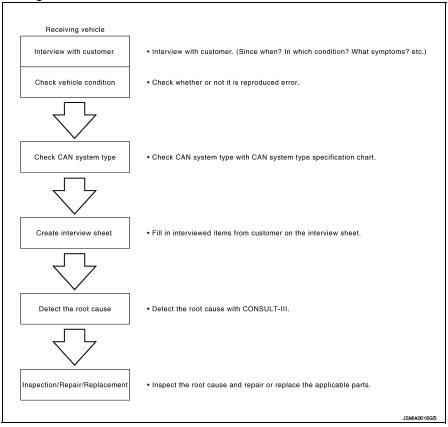
Trouble Diagnosis Procedure
INTERVIEW WITH CUSTOMER
Interview with the customer is important to detect the root cause of CAN communication system errors and to understand vehicle condition and symptoms for proper trouble diagnosis.
Points in interview
• What: Parts name, system name
• When: Date, Frequency
• Where: Road condition, Place
• In what condition: Driving condition/environment
• Result: Symptom
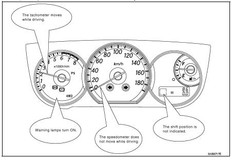
Notes for checking error symptoms: • Check normal units as well as error symptoms.
• Check normal units as well as error symptoms.
- Example: Circuit between ECM and the combination meter is judged normal if the customer indicates tachometer functions normally.
• When a CAN communication system error is present, multiple control units may malfunction or go into failsafe mode.
• Indication of the combination meter is important to detect the root cause because it is the most obvious to the customer, and it performs CAN communication with many units.
INSPECTION OF VEHICLE CONDITION
Check whether the symptom is reproduced or not.
NOTE
:
Do not turn the ignition switch OFF or disconnect the battery cable while
reproducing the error. The error may
temporarily correct itself, making it difficult to determine the root cause.
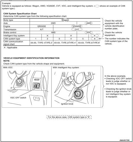
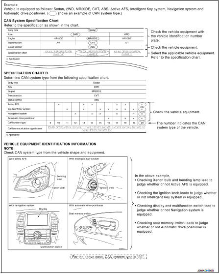
CHECK OF CAN SYSTEM TYPE (HOW TO USE CAN SYSTEM TYPE SPECIFICATION CHART)
Determine CAN system type based on vehicle equipment.
NOTE
:
• This chart is used if CONSULT-III does not automatically recognize CAN system
type.
• There are two styles for CAN system type specification charts. Depending on the number of available system types, either style A or style B may be used.
CAN System Type Specification Chart (Style A) NOTE
: CAN system type is easily checked with the vehicle equipment identification information shown in the chart.
CAN System Type Specification Chart (Style B)
NOTE
: CAN system type is easily checked with the vehicle equipment identification information shown in the chart.
CREATE INTERVIEW SHEET
Fill out the symptom described by the customer, vehicle condition, and CAN system type on the interview sheet.
Interview Sheet (Example)

DETECT THE ROOT CAUSE
CAN diagnosis function of CONSULT-III detects the root cause.
 Trouble diagnosis
System Diagram
Condition of Error Detection
DTC (e.g. U1000 and U1001) of CAN communication is indicated on SELF-DIAG
RESULTS on CONSULT-III
if a CAN communication signal is not transmitted o ...
 LAN system can
...
Other materials:
Diagnosis and repair work flow
Work Flow
OVERALL SEQUENCE
DETAILED FLOW
1.GET INFORMATION ABOUT SYMPTOM
Get detailed information from the customer about the symptom (the condition
and the environment when the
incident/malfunction occurs).
>> GO TO 2.
2.CHECK DTC
1. Check DTC of “ENGINE”, “BCM” and †...
S mode indicator
Component Function Check
1.CHECK S MODE INDICATOR FUNCTION
Check S mode indicator turns ON for approx. 2 seconds when ignition switch
turns ON.
Is the inspection results normal?
YES >> INSPECTION END
NO >> Go to TM-469, "Diagnosis Procedure".
Diagnosis Procedure
1.CH ...
Brake system
BRAKING PRECAUTIONS
The brake system has two separate hydraulic circuits. If one circuit malfunctions,
you will still have braking at two wheels.
You may feel a small click and hear a sound when the brake pedal is fully depressed
slowly.
This is not a malfunction and indicates that the brake ...
