Nissan Juke Service and Repair Manual : Trouble diagnosis
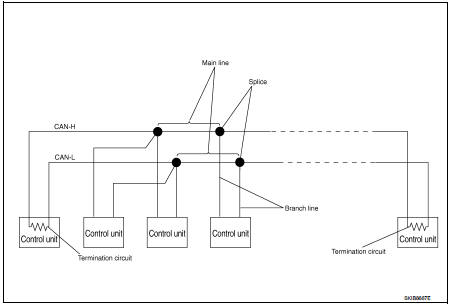
System Diagram
Condition of Error Detection
DTC (e.g. U1000 and U1001) of CAN communication is indicated on SELF-DIAG RESULTS on CONSULT-III if a CAN communication signal is not transmitted or received between units for 2 seconds or more.
CAN COMMUNICATION SYSTEM ERROR
• CAN communication line open (CAN-H, CAN-L, or both)
• CAN communication line short (ground, between CAN communication lines, other
harnesses)
• Error of CAN communication control circuit of the unit connected to CAN
communication line
WHEN DTC OF CAN COMMUNICATION IS INDICATED EVEN THOUGH CAN COMMUNICATION SYSTEM IS NORMAL
• Removal/installation of parts: Error may be detected when removing and
installing CAN communication unit
and related parts while turning the ignition switch ON. (A DTC except for CAN
communication may be
detected.)
• Fuse blown out (removed): CAN communication of the unit may cease.
• Voltage drop: Error may be detected if voltage drops due to discharged battery when turning the ignition switch ON (Depending on the control unit which carries out CAN communication).
• Error may be detected if the power supply circuit of the control unit, which carries out CAN communication, malfunctions (Depending on the control unit which carries out CAN communication).
• Error may be detected if reprogramming is not completed normally.
CAUTION
:
CAN communication system is normal if DTC of CAN communication is indicated on
SELF-DIAG
RESULTS of CONSULT-III under the above conditions. Erase the memory of the
self-diagnosis of each
unit.
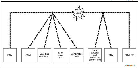
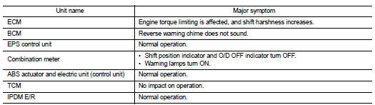
Symptom When Error Occurs in CAN Communication System
In CAN communication system, multiple units mutually transmit and receive signals. Each unit cannot transmit and receive signals if any error occurs on CAN communication line. Under this condition, multiple control units related to the root cause malfunction or go into fail-safe mode.
ERROR EXAMPLE
NOTE
:
Each vehicle differs in symptom of each unit under fail-safe mode and CAN
communication line wiring.
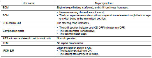
Example: Main Line Between Data Link Connector and ABS Actuator and Electric Unit (Control Unit) Open Circuit
Example: TCM Branch Line Open Circuit
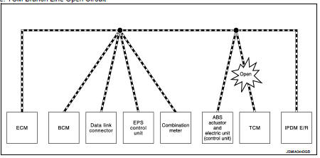
NOTE
:
The model (all units on CAN communication system are Diag on CAN) cannot perform
CAN diagnosis with
CONSULT-III if the following error occurs. The error is judged by the symptom.
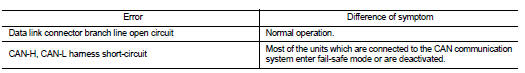
Example: Data Link Connector Branch Line Open Circuit
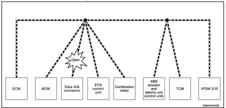
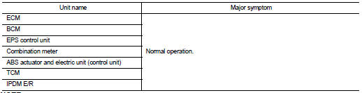
NOTE
:
When data link connector branch line is open, transmission and reception of CAN
communication signals are
not affected. Therefore, no symptoms occur. However, be sure to repair
malfunctioning circuit.
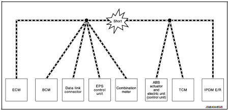
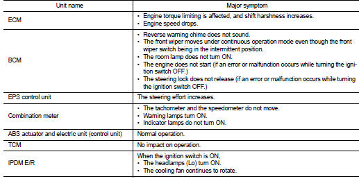
Example: CAN-H, CAN-L Harness Short Circuit
Can diagnosis with consult-III
CAN diagnosis on CONSULT-III extracts the root cause by receiving the following information.
• Response to the system call
• Control unit diagnosis information
• Self-diagnosis
• CAN diagnostic support monitor
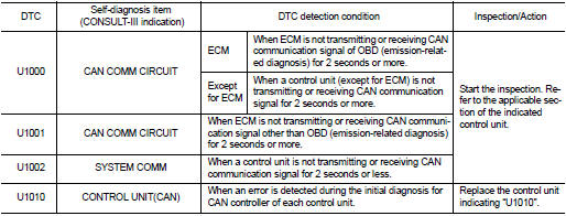
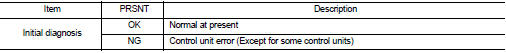
Self-Diagnosis
If communication signals cannot be transmitted or received among units communicating via CAN communication line, CAN communication-related DTC is displayed on the CONSULT-III “Self Diagnostic Result” screen.
NOTE
:
The following table shows examples of CAN communication-related DTC. For other
DTC, refer to the applicable
sections.
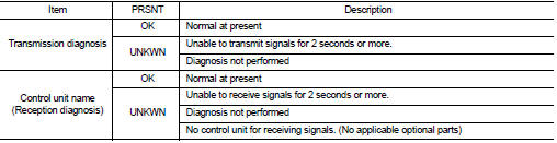
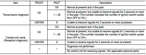
Can Diagnostic Support Monitor
MONITOR ITEM (CONSULT-III)
Example: CAN DIAG SUPPORT MNTR indication
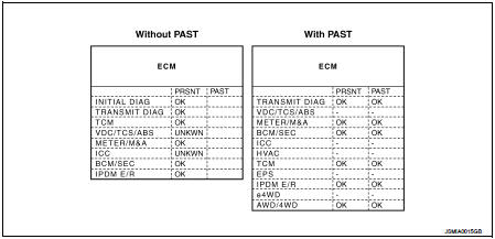
Without PAST
With PAST
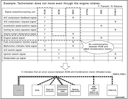
How to Use Can Communication Signal Chart
The CAN communication signal chart lists the signals needed for trouble diagnosis. It is useful for detecting the root cause by finding a signal related to the symptom, and by checking transmission and reception unit.
 System
Can communication system
CAN COMMUNICATION SYSTEM : System Description
CAN (Controller Area Network) is a serial communication line for real time
application. It is an on-vehicle multiplex
commun ...
 Basic inspection
Diagnosis and repair workflow
Trouble Diagnosis Flow Chart
Trouble Diagnosis Procedure
INTERVIEW WITH CUSTOMER
Interview with the customer is important to detect the root cause of CAN
communic ...
Other materials:
Removal and installation
MULTI DISPLAY UNIT
Exploded View
REMOVAL
Refer to IP-12, "Exploded View".
DISASSEMBLY
1. Silencer tape
2. Multi display unit
3. Silencer tape
4. Clip
5. Control finisher
Removal and Installation
REMOVAL
Refer to IP-12, "Exploded View".
CAUTION:
• When per ...
Driving the vehicle
Electric shift control system
This sophisticated vehicle is electronically controlled by an advanced powertrain management unit to produce maximum available torque, rapid throttle acceleration, and smooth, seamless operation under all regular driving conditions.
The factory rec ...
P0327, P0328 KS
DTC Logic
DTC DETECTION LOGIC
DTC CONFIRMATION PROCEDURE
1.PRECONDITIONING
If DTC Confirmation Procedure has been previously conducted, always perform
the following procedure
before conducting the next test.
1. Turn ignition switch OFF and wait at least 10 seconds.
2. Turn ignition swit ...
