Nissan Juke Service and Repair Manual : Preparation
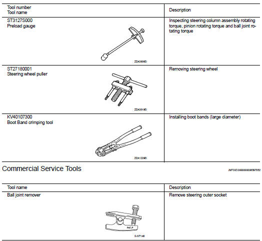
Special Service Tools
BASIC INSPECTION
STEERING WHEEL
Inspection
NEUTRAL POSITION STEERING WHEEL
1. Make sure that steering gear assembly, steering column assembly and steering wheel are installed in the correct position.
2. Perform neutral position inspection after wheel alignment. Refer to FSU-7, "Inspection".
3. Set vehicle to the straight-ahead position and confirm steering wheel is in the neutral position.
4. Loosen outer socket lock nut and turn inner socket to left and right equally to make fine adjustments if steering wheel is not in the neutral position.
STEERING WHEEL TURNING FORCE
1. Park vehicle on a level and dry surface, set parking brake.
2. Tires need to be inflated normal pressure. Refer to WT-9, "Tire Air Pressure".
3. Start engine.
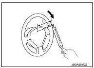
4. Check steering wheel turning force when steering wheel has been turned 360┬░ from neutral position.
Steering wheel turning force : Refer to ST-23, "Steering Wheel Turning Force".
L : 185 mm (7.28 in)
NOTE
:
Multiply the distance from the hook of spring balance to the center
of steering wheel by the measurement value with a spring
balance.
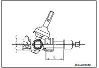
FRONT WHEEL TURNING ANGLE
1. Check front wheel turning angle after toe-in inspection. Refer to FSU-7, "Inspection".
2. Place front wheels on turning radius gauges and rear wheels on stands, so that vehicle can be level.
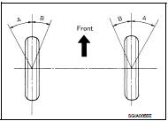
3. Check the maximum inner and outer wheel turning angles for LH and RH road wheels.
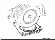
4. With the engine at idle, turn steering wheel from full left stop to full right stop and measure the turning angles.
Inner wheel (Angle: A) : Refer to ST-23, "Steering Angle".
Outer wheel (Angle: B) : Refer to ST-23, "Steering Angle".
5. Check the following items when turning angle is out of the standard.
a. Check rack stroke (L).
L : Refer to ST-23, "Rack Stroke".
b. If rack stroke is out of specification, replace steering gear assembly.
ÔÇó Steering angles are not adjustable. Check steering gear assembly, steering column assembly, and front suspension components for wear or damage if any of the turning angles are different from the specified value. Replace any of them, if any non-standard condition exists.
 Service Notice or Precautions for Steering System
ÔÇó In case of removing steering gear assembly, make the final tightening with
grounded and unloaded vehicle
condition, and then check wheel alignment.
ÔÇó Observe the following precautions when d ...
 Symptom diagnosis
NOISE, VIBRATION AND HARSHNESS (NVH) TROUBLESHOOTING
NVH Troubleshooting Chart
Use the chart below to find the cause of the symptom. If necessary, repair or
replace these parts.
×: Applic ...
Other materials:
P0703 brake switch B
Description
BCM detects ON/OFF state of the stop lamp switch and transmits the data to
the CVT control unit via CAN
communication by converting the data to a signal.
DTC Logic
DTC DETECTION LOGIC
DTC CONFIRMATION PROCEDURE
CAUTION:
Always drive vehicle at a safe speed.
NOTE:
If ÔÇťDTC C ...
G sensor
Exploded View
1. Bracket
2. G sensor
: Vehicle front
: N┬Ěm (kg-m, ft-lb)
: N┬Ěm (kg-m, in-lb)
Removal and Installation
CAUTION:
ÔÇó Never drop or strike G sensor, because it has little tolerance for impact.
ÔÇó Never use a power tool to avoid impact.
REMOVAL
1. Disconnect the battery ...
Precaution for Supplemental Restraint System (SRS) "AIR BAG" and "SEAT BELT
PRE-TENSIONER"
The Supplemental Restraint System such as ÔÇťAIR BAGÔÇŁ and ÔÇťSEAT BELT
PRE-TENSIONERÔÇŁ, used along
with a front seat belt, helps to reduce the risk or severity of injury to the
driver and front passenger for certain
types of collision. Information necessary to service the system safely is
...
