Nissan Juke Service and Repair Manual : B1006, B1007, B1008, B1009, B1010 diagnosis sensor unit
DTC Logic
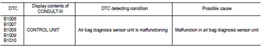
DTC DETECTION LOGIC
DTC CONFIRMATION PROCEDURE
1.CHECK SELF-DIAG RESULT
 With CONSULT-III
1. Turn ignition switch ON.
2. Perform “Self Diagnostic Result” mode of “AIR BAG” using CONSULT-III.
 Without CONSULT-III
1. Turn ignition switch ON.
2. Check the air bag warning lamp status. Refer to SRC-12, "On Board Diagnosis Function".
NOTE
:
SRS does not enter the diagnosis mode if no malfunction is detected in the user
mode.
Is malfunctioning part detected? YES >> Refer to SRC-30, "Diagnosis Procedure".
NO >> INSPECTION END
Diagnosis Procedure
WARNING:
• Before servicing, turn ignition switch OFF, disconnect battery negative
terminal, and wait 3 minutes
or more. (To discharge backup capacitor.)
• Never use unspecified tester or other measuring device.
1.CHECK HARNESS CONNECTOR
Check the harness connector.
Is the inspection result normal? YES >> GO TO 2.
NO >> Replace harness connectors.
2.CHECK WIRING HARNESS
Check the wiring harness externals.
Is the inspection result normal? YES >> GO TO 3.
NO >> Replace wiring harness.
3.REPLACE AIR BAG DIAGNOSIS SENSOR UNIT
1. Replace air bag diagnosis sensor unit. Refer to SR-30, "Removal and Installation".
2. Perform DTC confirmation procedure. Refer to SRC-30, "DTC Logic".
Is DTC detected? YES >> GO TO 1.
NO >> INSPECTION END
 B1001, B1002, B1003, B1004, B1005 diagnosis sensor unit
DTC Logic
DTC DETECTION LOGIC
DTC CONFIRMATION PROCEDURE
1.CHECK SELF-DIAG RESULT
With CONSULT-III
1. Turn ignition switch ON.
2. Perform “Self Diagnostic Result” mode of “AIR BAG” usi ...
 B1011, B1012, B1013, B1014, B1015 diagnosis sensor unit
DTC Logic
DTC DETECTION LOGIC
DTC CONFIRMATION PROCEDURE
1.CHECK SELF-DIAG RESULT
With CONSULT-III
1. Turn ignition switch ON.
2. Perform “Self Diagnostic Result” mode of “AIR BAG” usi ...
Other materials:
Precaution for Brake System
WARNING:
Clean any dust from the front brake and rear brake with a vacuum dust collector.
Never blow with compressed
air.
• Brake fluid use refer to MA-13, "Fluids and Lubricants".
• Never reuse drained brake fluid.
• Never spill or splash brake fluid on painted surfaces. Brak ...
P158A ECM
DTC Logic
*: Since this DTC is detected when G sensor calibration is incomplete, there
is not replacement parts.
1.PRECONDITIONING
If DTC Confirmation Procedure has been previously conducted, always perform
the following procedure
before conducting the next test.
1. Turn ignition swit ...
P0715 input speed sensor A
DTC Logic
DTC DETECTION LOGIC
DTC CONFIRMATION PROCEDURE
CAUTION:
Always drive vehicle at a safe speed.
NOTE:
If “DTC CONFIRMATION PROCEDURE” has been previously performed, always turn
ignition switch
OFF and wait at least 10 seconds before performing the next test.
After the repai ...
