Nissan Juke Service and Repair Manual : A/C on signal
Component Function Check
1.CHECK A/C ON SIGNAL
 With CONSULT-III
1. Turn ignition switch ON.
2. Operate blower motor.
3. Select “AIR CONDITIONER” of “BCM” using CONSULT-III.
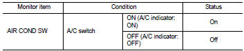
4. Select “AIR COND SW” in “DATA MONITOR” mode.
5. Check A/C ON signal when the A/C switch is operated.
Is the inspection result normal? YES >> INSPECTION END
NO >> Refer to HAC-75, "Diagnosis Procedure".
Diagnosis Procedure
1.CHECK A/C ON SIGNAL
1. Turn ignition switch OFF.
2. Disconnect A/C auto amp. connector.
3. Turn ignition switch ON.
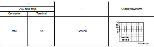
4. Check output waveform between A/C auto amp. harness connector and ground with using oscilloscope
Is the inspection result normal? YES >> Replace A/C auto amp. Refer to HAC-91, "Removal and Installation".
NO >> GO TO 2.
2.CHECK A/C ON SIGNAL CIRCUIT FOR OPEN
1. Turn ignition switch OFF.
2. Disconnect BCM connector.
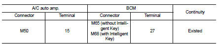
3. Check continuity between A/C auto amp. harness connector and BCM harness connector.
Is the inspection result normal? YES >> GO TO 3.
NO >> Repair harness or connector.
3.CHECK A/C ON SIGNAL CIRCUIT FOR SHORT
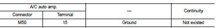
Check continuity between A/C auto amp. harness connector and ground.
Is the inspection result normal? YES >> Replace BCM. Refer to BCS-93, "Removal and Installation" (with Intelligent Key) or BCS-161, "Removal and Installation" (without Intelligent Key).
NO >> Repair harness or connector.
 Power supply and ground circuit
A/C auto AMP. : Diagnosis Procedure
1.CHECK SYMPTOM
Check symptom (A or B).
Which symptom is detected?
A >> GO TO 2.
B >> GO TO 5.
2.CHECK FUSE
1. Turn ignition switch OFF.
2 ...
 Blower fan on signal
Component Function Check
1.CHECK BLOWER FAN ON SIGNAL
With CONSULT-III
1. Turn ignition switch ON.
2. Select “AIR CONDITIONER” of “BCM” using CONSULT-III.
3. Select “FAN ON SIG” in †...
Other materials:
P1616 ECM
DTC Logic
DTC DETECTION LOGIC
DTC CONFIRMATION PROCEDURE
1.PERFORM DTC CONFIRMATION PROCEDURE FOR MALFUNCTION
1. Turn ignition switch ON amd wait 2 seconds or more.
2. Check DTC in “Self Diagnostic Result” mode of “ENGINE” using CONSULT-III.
Is DTC detected?
YES >> Go to SEC ...
SRS air bag warning lamp does not turn on
Diagnosis Procedure
1.CHECK COMBINATION METER POWER SUPPLY AND GROUND CIRCUIT
Check conbination meter unit power supply and ground circuit. Refer to
MWI-51, "COMBINATION METER :
Diagnosis Procedure".
Is the inspection result normal?
YES >> GO TO 2.
NO >> Repair or r ...
Structure and operation
Positive Crankcase Ventilation
This system returns blow-by gas to the intake manifold.
The positive crankcase ventilation (PCV) valve is provided to conduct crankcase
blow-by gas to the intake
manifold.
During partial throttle operation of the engine, the intake manifold sucks the
blow ...
