Nissan Juke Service and Repair Manual : Component parts
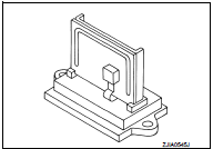
Component Part Location
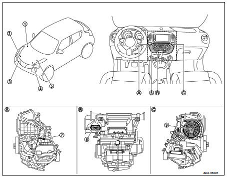
1. BCM
• With Intelligent Key: Refer to BCS-
6, "BODY CONTROL SYSTEM :
Component Parts Location".
• Without Intelligent Key: Refer to BCS-96, "BODY CONTROL SYSTEM : Component Parts Location".
2. Magnet clutch
3. Refrigerant pressure sensor
4. ECM
Refer to EC-25, "ENGINE CONTROL
SYSTEM :
Component Parts Location".
5. IPDM E/R
• With Intelligent Key: Refer to PCS-
5, "Component Parts Location".
• Without Intelligent Key: Refer to PCS-37, "Component Parts Location".
6. A/C control
7. Thermo control amp.
8. Blower fan resistor
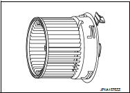
9. Blower motor
A. Left side of A/C unit assembly B. Back side of A/C unit assembly C. Right side of A/C unit assembly
Component Description
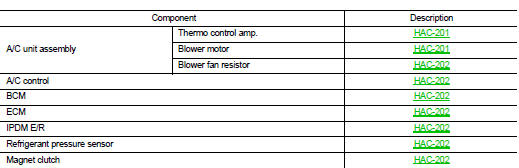
A/C unit assembly : Thermo Control Amp.
• Thermo control amp. is composed of thermistor and amplifier. Thermistor is installed on evaporator, and amplifier is attached to foot duct.
• When the thermistor detecting temperature of the evaporator fin is extremely low, thermo control amp. sends the thermo control amp. OFF signal to BCM, and stops the compressor.
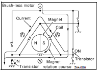
A/C unit assembly : Blower Motor
• The blower motor utilizes a brush-less motor with a rotating magnet.
• Quietness is improved over previous motors where the brush was the point of contact and the coil rotated.
A/C unit assembly : Blower Fan Resistor
• Compact and lightweight resistor is adopted with outstanding ventilation.
• Temperature fuse is installed to protects the blower motor circuit.
A/C Control
Controls the air conditioning function.
BCM
BCM transmits A/C ON signal and blower fan ON signal to ECM via CAN communication, according to A/C switch signal and blower fan ON signal that are received from A/C control and thermo control amp. signal that is received from thermo control amp. and A/C indicator is turned ON.
ECM
ECM, when receiving A/C ON signal and blower fan ON signal from BCM, transmits A/C compressor request signal to IPDM E/R via CAN communication according to status of the engine and refrigerant pressure.
IPDM E/R
A/C relay is integrated in IPDM E/R. IPDM E/R operates A/C relay when A/C compressor request signal is received from ECM via CAN communication line.
Refrigerant Pressure Sensor
DESCRIPTION
• The refrigerant pressure sensor converts high-pressure side refrigerant pressure into voltage and outputs it to ECM.
• ECM operates cooling system protection and idle speed control according to voltage value that is input.
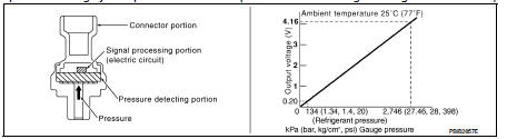
STRUCTURE AND OPERATION
• The refrigerant pressure sensor is a capacitance type sensor. It consists of a pressure detection ares and a signal processing area.
• The pressure detection area, which is a variable capacity condenser, changes internal static capacitance according to pressure force.
• The signal processing area detects the static capacitance of the pressure detection area, converts the static capacitance into a voltage value, and transmits the voltage value to ECM.
Magnet Clutch
Compressor is driven by the magnet clutch which is magnetized by electric power supply.

 System
System Diagram
System Description
DESCRIPTION
• Manual air conditioning system is controlled by each function of thermo
control amp., BCM, ECM and IPDM
E/R.
• Fan speed of blower motor is ...
Other materials:
B210C starter control relay
DTC Logic
DTC DETECTION LOGIC
NOTE:
• If DTC B210C is displayed with DTC U1000, first perform the trouble diagnosis
for DTC U1000. Refer to
PCS-30, "DTC Logic".
• When IPDM E/R power supply voltage is low (Approx. 7 - 8 V for about 1
second), the DTC B210C may be
detected.
...
Fuel injector
Component Function Check
1.INSPECTION START
Turn ignition switch to START.
Is any cylinder ignited?
YES >> GO TO 2.
NO >> Go to EC-778, "Diagnosis Procedure".
2.CHECK FUEL INJECTOR FUNCTION
With CONSULT-III
1. Start engine.
2. Perform “POWER BALANCE” in “AC ...
Squeak and rattle trouble diagnoses
Work Flow
CUSTOMER INTERVIEW
Interview the customer if possible, to determine the conditions that exist
when the noise occurs. Use the Diagnostic
Worksheet during the interview to document the facts and conditions when the
noise occurs and any of
the customer's comments; refer to DLK-139, &q ...
