Nissan Juke Service and Repair Manual : Structure and operation
Sectional View
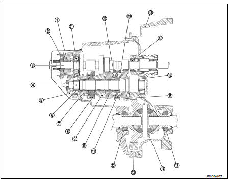
1. 5th input gear
2. 5th-reverse synchronizer hub assembly
3. Input shaft
4. Mainshaft
5. 5th main gear
6. Mainshaft rear bearing
7. 4th main gear
8. 3rd-4th synchronizer hub assembly
9. 3rd main gear
10. 2nd main gear
11. 1st-2nd synchronizer hub assembly
12. Differential side bearing
13. Final gear
14. Differential
15. 1st main gear
16. Mainshaft front bearing
17. Input shaft front bearing
18. Clutch housing
19. 1st double-cone synchronizer
20. 2nd double-cone synchronizer
21. Input shaft rear bearing
System Description
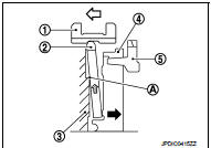
DOUBLE-CONE SYNCHRONIZER
Double-cone synchronizers are adopted for 1st and 2nd gears to reduce operating force of the shifter lever
1 : Outer baulk ring
2 : 2nd main gear
3 : Synchronizer cone
4 : Inner baulk ring
5 : 1st main gear
6 : 1st-2nd coupling sleeve
REVERSE GEAR NOISE PREVENTION FUNCTION (REVERSE BRAKE)
Description
Soon after the clutch is disengaged, the input shaft is still rotating due to
inertia. This may cause a gear noise
when the gear is shifted to reverse position. The reverse gear noise prevention
function stops the rotation of
the input shaft and enables smooth gear shifting when the reverse gear is
selected.
Operation Principle
1. When the gear is shifted to reverse position, 5th-reverse coupling
sleeve (1) slides in the reverse direction. (
)
5 : 5th input gear
2. Synchronizer levers (2) with support point (A) at 5th-reverse
synchronizer hub (3) presses 5th-reverse baulk ring (4). (
)
3. Friction that is generated at 5-reverse baulk ring presses synchronizer
lever on 5th-reverse coupling sleeve. (
)
4. 5th-reverse coupling sleeve that is pressed by synchronizer
lever stops the rotation of input shaft.
 Component parts
Component Parts Location
POSITION SWITCH
1 : Position switch
...
 DTC/Circuit diagnosis
POSITION SWITCH
BACK-UP LAMP SWITCH : Component Inspection
1.CHECK BACK-UP LAMP SWITCH
1. Disconnect position switch connector. Refer to TM-24, "Removal and
Installation".
2. Check con ...
Other materials:
Back door does not opened
Diagnosis Procedure
1.CHECK BACK DOOR OPENER SWITCH
Check back door opener switch.
Refer to DLK-69, "Component Function Check".
Is the inspection result normal?
YES >> GO TO 2.
NO >> Repair or replace the malfunctioning parts.
2.CHECK BACK DOOR OPENER ACTUATOR
C ...
Booster seats
For detailed guidance on safely installing a booster seat within your Nissan Leaf, please carefully follow the instructions and safety standards outlined in this section.
Precautions on booster seats
WARNING
Improper use of a booster seat or the vehicle's seat belt significantly incre ...
Front-seat Active Head Restraints
The Active Head Restraint moves forward utilizing the force that the seatback
receives from the occupant in a rear-end collision. The movement of the head restraint
helps support the occupant’s head by reducing its backward movement and helping
absorb some of the forces that may lead to wh ...
