Nissan Juke Service and Repair Manual : Component parts
Component Parts Location
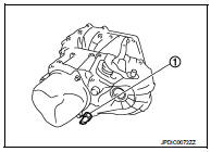
POSITION SWITCH
1 : Position switch

 Structure and operation
Sectional View
1. 5th input gear
2. 5th-reverse synchronizer hub assembly
3. Input shaft
4. Mainshaft
5. 5th main gear
6. Mainshaft rear bearing
7. 4th main gear
8. 3rd-4th synchronizer ...
Other materials:
Vehicle speed sensing auto lock operation does not operate
Diagnosis Procedure
1.CHECK “AUTOMATIC LOCK/UNLOCK SELECT” SETTING IN “WORK SUPPORT”
1. Select “DOOR LOCK” of “BCM” using CONSULT-III.
2. Select “AUTOMATIC LOCK/UNLOCK SELECT” in “WORK SUPPORT” mode.
3. Check “AUTOMATIC LOCK/UNLOCK SELECT” setting in “WORK SUPPORT†...
RearView Monitor system limitations
WARNING
Listed below are the inherent technical system limitations of the RearView Monitor equipment. Failure to operate your vehicle in accordance with these specific system limitations could cause blind spots to go unnoticed, resulting in serious personal injury or death.
The c ...
Hazard switch
Component Function Check
1.CHECK HAZARD SWITCH SIGNAL BY CONSULT-III
CONSULT-III DATA MONITOR
1. Turn the ignition switch ON.
2. Select “HAZARD SW” of BCM (FLASHER) data monitor item.
3. With operating the hazard switch, check the monitor status.
Is the inspection result normal?
YES > ...
