Nissan Juke Service and Repair Manual : DTC/Circuit diagnosis
POSITION SWITCH
BACK-UP LAMP SWITCH : Component Inspection
1.CHECK BACK-UP LAMP SWITCH
1. Disconnect position switch connector. Refer to TM-24, "Removal and Installation".
2. Check continuity between position switch terminals.

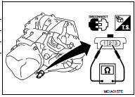
Is the inspection result normal? YES >> INSPECTION END
NO >> Replace position switch. Refer to TM-24, "Removal and Installation".
PARK/NEUTRAL POSITION (PNP) SWITCH : Component Inspection
1.CHECK PARK/NEUTRAL POSITION (PNP) SWITCH
1. Disconnect position switch connector. Refer to TM-24, "Removal and Installation".
2. Check continuity between position switch terminals.

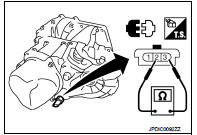
Is the inspection result normal? YES >> INSPECTION END
NO >> Replace position switch. Refer to TM-24, "Removal and Installation".
 Structure and operation
Sectional View
1. 5th input gear
2. 5th-reverse synchronizer hub assembly
3. Input shaft
4. Mainshaft
5. 5th main gear
6. Mainshaft rear bearing
7. 4th main gear
8. 3rd-4th synchronizer ...
 Symptom diagnosis
NOISE, VIBRATION AND HARSHNESS (NVH) TROUBLESHOOTING
NVH Troubleshooting Chart
Use the chart below to find the cause of the symptom. The numbers indicate
the order of the inspection. If necessary, ...
Other materials:
Component parts
Component Parts Location
1. Light & rain sensor*1
2. Combination switch
3. Combination meter
4. BCM
Refer to BCS-6, "BODY CONTROL
SYSTEM : Component Parts Location".
5. IPDM E/R
Refer to PCS-5, "Component Parts
Location" (with Intelligent Key system)
or PCS-37, ...
B1121 satellite sensor LH
DTC Logic
DTC DETECTION LOGIC
DTC CONFIRMATION PROCEDURE
1.CHECK SELF-DIAG RESULT
With CONSULT-III
1. Turn ignition switch ON.
2. Perform “Self Diagnostic Result” mode of “AIR BAG” using CONSULT-III.
Without CONSULT-III
1. Turn ignition switch ON.
2. Check the air bag warning la ...
Three-point type seat belt
WARNING
• Every person who drives or rides in this vehicle should use a seat belt
at all times.
• Do not ride in a moving vehicle when the seatback is reclined. This can be dangerous.
The shoulder belt will not be against your body. In an accident, you could be thrown
into it and receive ...
