Nissan Juke Service and Repair Manual : System
System Diagram
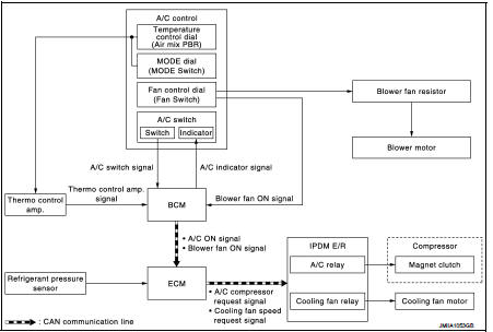
System Description
DESCRIPTION
ŌĆó Manual air conditioning system is controlled by each function of thermo control amp., BCM, ECM and IPDM E/R.
ŌĆó Fan speed of blower motor is changed by the combination of fan control dial operation and blower fan resistor control.
CONTROL BY THERMO CONTROL AMP.
HAC-203, "Compressor Control"
CONTROL BY BCM
HAC-203, "Compressor Control"
CONTROL BY ECM
ŌĆó HAC-203, "Compressor Control" ŌĆó Cooling fan control: Refer to EC-61, "COOLING FAN CONTROL : System Description".
CONTROL BY IPDM E/R
ŌĆó HAC-203, "Compressor Control"
ŌĆó Cooling fan control
- With Intelligent Key system: Refer to PCS-9, "POWER CONTROL SYSTEM : System Description".
- Without Intelligent Key system: Refer to PCS-41, "POWER CONTROL SYSTEM : System Description"
Compressor Control
DESCRIPTION
ŌĆó BCM transmits the A/C ON signal and blower fan ON signal to ECM via CAN communication line only when the compressor operational condition is satisfied, and A/C indicator is turned ON.
Refer to BCS-13, "SIGNAL BUFFER SYSTEM : System Description" (with Intelligent Key system) or BCS- 103, "SIGNAL BUFFER SYSTEM : System Description" (without Intelligent Key system).
NOTE
:
Compressor operational condition
ŌĆó A/C switch signal: ON
ŌĆó Blower fan ON signal: ON
ŌĆó Thermo control amp. signal: ON
ŌĆó ECM judges the conditions of each sensor (Refrigerant pressure sensor signal,
accelerator position signal,
etc.), and transmits the A/C compressor request signal to IPDM E/R via CAN
communication line.
ŌĆó By receiving the A/C compressor request signal from ECM, IPDM E/R turns the A/C relay to ON, and activates the compressor.
Refer to PCS-6, "RELAY CONTROL SYSTEM : System Description" (with Intelligent Key system) or PCS- 38, "RELAY CONTROL SYSTEM : System Description" (without Intelligent Key system).
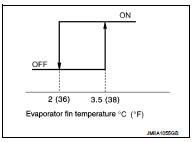
CONTROL BY THERMO CONTROL AMP.
Low Temperature Protection Control ŌĆó When the thermo control amp. detects that evaporator fin temperature is 2┬░C (36┬░F) or less, thermo control amp. signal becomes OFF, and stops the compressor.
ŌĆó When the air temperature returns to 3.5┬░C (38┬░F) or more, the compressor is activated.
CONTROL BY ECM
Compressor Protection Control at Pressure Malfunction The high-pressure side value that is detected by refrigerant pressure sensor is as per the following state, ECM requests IPDM E/R to turn A/C relay OFF and stop the compressor.
ŌĆó 3.12 MPa (31.82 kg/cm2, 452.4 psi) or more (When the engine speed is less than
1,500 rpm)
ŌĆó 2.74 MPa (27.95 kg/cm2, 397.3 psi) or more (When the engine speed is 1,500 rpm
or more)
ŌĆó 0.14 MPa (1.43 kg/cm2, 20.3 psi) or less
Compressor Oil Circulation Control When the engine starts while the engine coolant temperature is 56┬░C (133┬░F) or less, ECM activates the compressor for approximately 6 seconds and circulates the compressor oil once.
Air Conditioning Cut Control When the engine condition is high load, ECM makes the A/C relay to OFF, and stops the compressor.
Refer to EC-60, "AIR CONDITIONING CUT CONTROL : System Description".
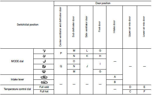
Door Control
SWITCHES AND THEIR CONTROL FUNCTIONS
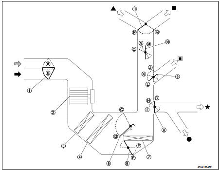
1. Intake door
2. Blower motor
3. Air conditioner filter
4. Evaporator
5. Upper air mix door
6. Lower air mix door
7. Heater core
8. Foot door
9. Side ventilator door
10. Sub defroster door
11. Center ventilator and defroster door
 Fresh air intake
 Recirculation air
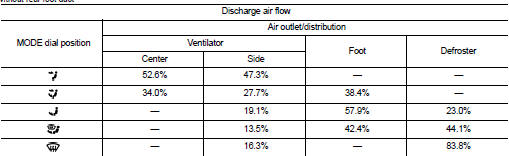
 Defroster
 Center ventilator
 Side ventilator
 Foot
Foot
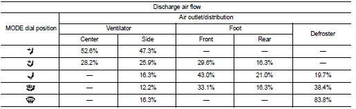
 Rear foot*
*: With rear foot duct
AIR DISTRIBUTION
Without rear foot duct
With rear foot duct
 Component parts
Component Part Location
1. BCM
ŌĆó With Intelligent Key: Refer to BCS-
6, "BODY CONTROL SYSTEM :
Component Parts Location".
ŌĆó Without Intelligent Key: Refer to
BCS-96, "BODY C ...
 Operation
Switch Name and Function
A/C CONTROLLER (A/C CONTROL)
1. MODE dial
2. Fan control dial
3. A/C switch
4. Temperature control dial
5. Intake lever
...
Other materials:
P1612 chain of ECM-IMMU
DTC Logic
DTC DETECTION LOGIC
NOTE:
ŌĆó If DTC P1612 is displayed with DTC U1000 (for BCM), first perform the trouble
diagnosis for DTC U1000.
Refer to BCS-153, "DTC Logic".
ŌĆó If DTC P1612 is displayed with DTC U1010 (for BCM), first perform the trouble
diagnosis for DTC U1010 ...
B2626 outside antenna
DTC Logic
DTC DETECTION LOGIC
DTC CONFIRMATION PROCEDURE
1.PERFORM DTC CONFIRMATION PROCEDURE
1. Disconnect outside key antenna (driver side) connector.
2. Perform ŌĆ£INTELLIGENT KEYŌĆØ Self Diagnostic Result.
Is outside key antenna DTC detected?
YES >> Refer to DLK-61, "Diagno ...
Brake booster
Inspection
OPERATION
Depress the brake pedal several times at 5-second intervals with the engine
stopped. Start the engine with the
brake pedal fully depressed. Check that the clearance between brake pedal and
dash lower panel decreases.
NOTE:
A slight impact with a small click may be fel ...
