Nissan Juke Service and Repair Manual : Component parts
Charging system
CHARGING SYSTEM : Component Parts Location
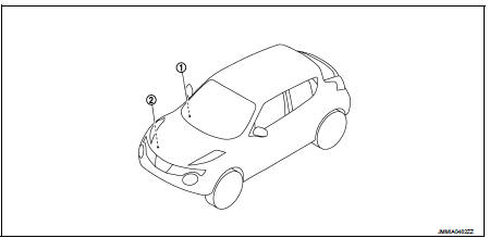
1. Charge warning lamp (On the combination
meter)
2. Alternat
CHARGING SYSTEM : Component Description
Power generation voltage variable control system
POWER GENERATION VOLTAGE VARIABLE CONTROL SYSTEM : Component Parts Location
NOTE:
This system is applied only for models with battery current sensor. The battery current sensor is installed to the battery cable at the negative terminal.
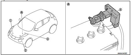
1. Alternator
2. ECM
Refer to EC-25, "ENGINE CONTROL
SYSTEM :
Component Parts Location"
(MR16DDT), EC-455, "ENGINE
CONTROL SYSTEM :
Component Parts Location"
(HR16DE), EC-813, "Component
Parts Location" (K9K).
3. IPDM E/R Refer to PCS-5, "Component Parts Location" (with Intelligent Key system), PCS-37, "Component Parts Location" (without Intelligent Key system).
4. Battery current sensor (with battery temperature sensor)
A. Battery
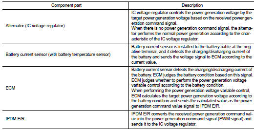
POWER GENERATION VOLTAGE VARIABLE CONTROL SYSTEM : Component Description

 System
Charging system
CHARGING SYSTEM : System Diagram
GASOLINE ENGINE MODELS
DIESEL ENGINE MODELS
CHARGING SYSTEM : System Description
The alternator provides DC voltage to operate the vehicle's e ...
Other materials:
Door lock operation warning does not operate
Diagnosis Procedure
1.CHECK DOOR LOCK FUNCTION
Check door lock function.
Does door lock/unlock using door request switch?
YES >> GO TO 2.
NO >> Refer to DLK-85, "Component Function Check".
2.CHECK INTELLIGENT KEY WARNING BUZZER
Check Intelligent Key warning buzzer. ...
Trouble diagnosis - specification
value
Description
The specification (SP) value indicates the tolerance of the value that is
displayed in “SPEC” of “DATA MONITOR”
mode of CONSULT-III during normal operation of the Engine Control System. When
the value in “SPEC”
of “DATA MONITOR” mode is within the SP value, the En ...
Shift position indicator circuit
Component Parts Function Inspection
1.CHECK SHIFT POSITION INDICATOR
1. Start the engine.
2. Shift selector lever.
3. Check that the selector lever position and the shift position indicator on
the combination meter are identical.
Is the inspection result normal?
YES >> INSPECTION END ...
