Nissan Juke Service and Repair Manual : System
Charging system
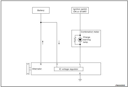
CHARGING SYSTEM : System Diagram
GASOLINE ENGINE MODELS
DIESEL ENGINE MODELS
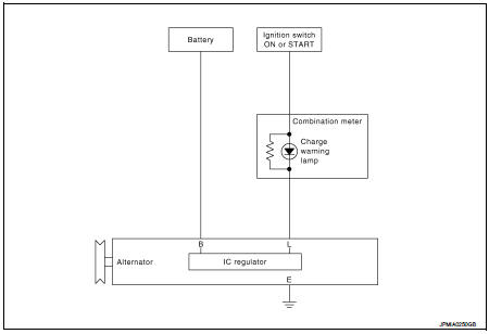
CHARGING SYSTEM : System Description
The alternator provides DC voltage to operate the vehicle's electrical system and to keep the battery charged.
The voltage output is controlled by the IC voltage regulator
Power generation voltage variable control system
POWER GENERATION VOLTAGE VARIABLE CONTROL SYSTEM : System Diagram (Gasoline Engine Models)
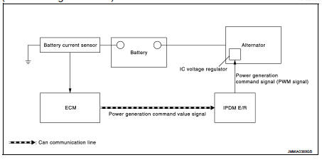
POWER GENERATION VOLTAGE VARIABLE CONTROL SYSTEM : System Description (Gasoline Engine Models)
By performing the power generation voltage variable control, the engine load due to the power generation of the alternator is reduced and fuel consumption is decreased.
NOTE
:
When any malfunction is detected in the power generation voltage variable
control system, the power generation
is performed according to the characteristic of the IC voltage regulator of the
alternator.
 Component parts
Charging system
CHARGING SYSTEM : Component Parts Location
1. Charge warning lamp (On the combination
meter)
2. Alternat
CHARGING SYSTEM : Component Description
Power generation voltage vari ...
 Wiring diagram
CHARGING SYSTEM
Wiring Diagram
GASOLINE ENGINE MODELS
For connector terminal arrangements, harness layouts, and alphabets in a
(option abbreviation; if not
described in wiring diagram), refer to ...
Other materials:
Precaution for Brake System
WARNING:
Clean any dust from the front brake and rear brake using a vacuum dust
collector. Never blow by compressed
air.
• Brake fluid use refer to MA-13, "Fluids and Lubricants".
• Never reuse drained brake fluid.
• Never spill or splash brake fluid on painted surfaces. Brake ...
Service
• Never use electrical test equipment to check SRS circuits unless instructed
to in this Service Manual.
• Before servicing the SRS, turn ignition switch OFF, disconnect battery
negative terminal and wait 3 minutes
or more. For approximately 3 minutes after the cables are removed, it is st ...
Light & rain sensor
Component Function Check
1.CHECK FRONT WIPER AUTO OPERATION
1. Clean rain sensor detection area of windshield fully.
2. When the front wiper switch is turned to AUTO position, front wiper operates
once regardless of a rainy
condition.
Is front wiper (AUTO) operation normally?
YES >> ...
