Nissan Juke Service and Repair Manual : Steering gear and linkage
Exploded View
REMOVAL
LHD Models
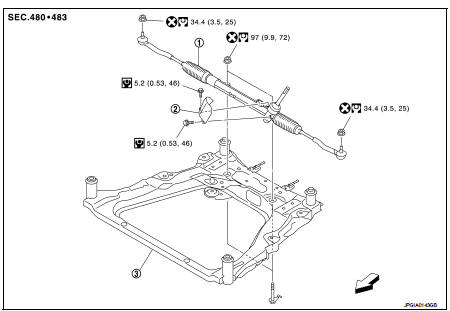
1. Steering gear assembly
2. Heat insulator
3. Front suspension member
 : Vehicle front
 : Always replace after every
disassembly.
 : N·m (kg-m, ft-lb)
 : N·m (kg-m, in-lb)
RHD Models
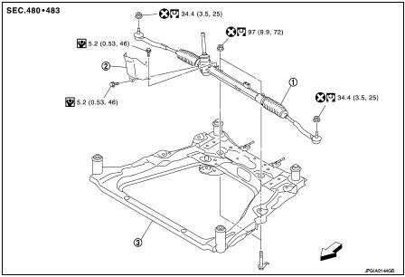
1. Steering gear assembly
2. Heat insulator
3. Front suspension member
: Vehicle front
: Always replace after every
disassembly.
: N·m (kg-m, ft-lb)
: N·m (kg-m, in-lb)
DISASSEMBLY
LHD models
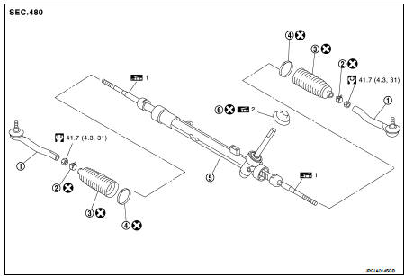
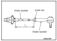
1. Outer socket
2. Boot clamp (small diameter)
3. Boot
4. Boot clamp (large diameter)
5. Steering gear assembly
6. Dust cover
 1: Apply Genuine Lithium Soap,
Autorex A (manufactured by Kyodo yushi) or equivalent.
 2: Apply Genuine Lithium Soap,
Wanlouver No.2 (manufactured by Kyodo yushi) or equivalent.
: Always replace after every
disassembly.
: N·m (kg-m, ft-lb)
RHD models
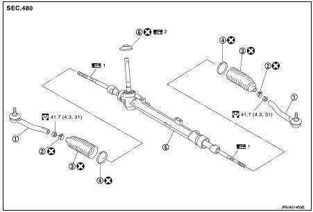
1. Outer socket
2. Boot clamp (small diameter)
3. Boot
4. Boot clamp (large diameter)
5. Steering gear assembly
6. Dust cover
1: Apply Genuine Lithium Soap,
Autorex A (manufactured by Kyodo yushi) or equivalent.
2: Apply Genuine Lithium Soap,
Wanlouver No.2 (manufactured by Kyodo yushi) or equivalent.
: Always replace after every
disassembly.
: N·m (kg-m, ft-lb)
Removal and Installation
REMOVAL
1. Set vehicle to the straight-ahead position.
2. Remove intermediate shaft mounting bolt (steering gear assembly side). Refer to ST-10, "Removal and Installation".
CAUTION:
• Spiral cable may be cut if steering wheel turns while separating steering
column assembly and
steering gear assembly. Always fix the steering wheel using string to avoid
turning.
• Place a matching mark on both intermediate shaft and steering gear assembly before removing intermediate shaft.
• When removing intermediate shaft, never insert a tool, such as a screwdriver, into the yoke groove to pull out the intermediate shaft. In case of the violation of the above, replace intermediate shaft with a new one.
3. Remove dash seal from vehicle. Refer to ST-14, "Removal and Installation".
4. Remove tires. Refer to WT-7, "Removal and Installation".
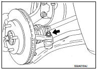
5. Remove steering outer socket from steering knuckle so as not to damage ball joint boot using suitable ball joint remover (commercial service tool).
CAUTION:
Temporarily tighten the nut to prevent damage to threads
and to prevent the ball joint remover from sudden drop
turning.
6. Remove front suspension member. Refer to FSU-18, "Removal and Installation".
7. Remove steering gear assembly.
INSTALLATION
Note the following, and install in the reverse order of removal.
CAUTION:
Spiral cable may be cut if steering wheel turns while separating steering column
assembly and steering
gear assembly. Always fix the steering wheel using string to avoid turning.
• Perform final tightening of nuts and bolts on each part under unladen conditions with tires on level ground when removing steering gear assembly. Check wheel alignment. Refer to FSU-7, "Inspection".
• Rotate steering wheel to check for decentered condition, binding, noise or excessive steering effort.
• Never reuse steering outer socket mounting nut and steering gear assembly mounting nut.
• Perform inspection after installation. Refer to ST-21, "Inspection".
Disassembly and Assembly
DISASSEMBLY
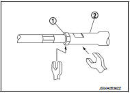
1. Loosen outer socket lock nut, and remove outer socket.
CAUTION:
When loosening lock nut, be sure to fix outer socket with a wrench or an equiv
alent.
2. Remove boot clamps, and then remove boot from inner socket.
CAUTION:
Never damage inner socket part and gear housing part of steering gear assembly
when removing
boot. steering gear assembly must be replaced if steering gear assembly are
damaged because it
may cause foreign material interfusion.
3. Remove dust cover.
4. Perform inspection after disassembly. Refer to ST-21, "Inspection".
ASSEMBLY
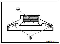
1. Apply recommended grease to the entire inner perimeter (A) of the dust cover lip and contact surface (B) of the gear housing part, and install dust cover to steering gear assembly.
Use Genuine Lithium Soap, Wanlouver No.2 (manufactured by Kyodo yushi) or equivalent
2. Apply recommended grease to inner socket (A) of steering gear assembly and install boot to steering gear assembly.
Use Genuine Lithium Soap, Autorex A (manufactured by Kyodo yushi) or equivalent.
CAUTION
:
Never reuse boot.
Grease application position (Reference) A : 10 mm (0.39 in)
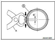
3. Install boot clamp (large diameter) (1) to boot using boot band crimping tool (A) (SST: KV40107300).
CAUTION:
• Never reuse boot clamp (large diameter).
• Install boot clamp (large diameter) (1) securely to boot groove, and crimp it so as to have clearance (B) of 3 mm (0.12 in) or less as shown.
4. Install boot clamp (small diameter) to boot.
CAUTION:
Never reuse boot clamp (small diameter).
5. Adjust inner socket to standard length (L), and then tighten lock nut to the specified torque. Check length again after tightening lock nut.
L : Refer to ST-24, "Inner Socket Length".
CAUTION:
• When tightening the lock nut (1), be sure to fix outer
socket (2) with a wrench or an equivalent to prevent the
ball joint from getting contact with the knuckle.
• Adjust toe-in. Refer to FSU-7, "Inspection". Length achieved after toe-in adjustment is not necessarily the above value.
Inspection
INSPECTION AFTER INSTALLATION
• Check if steering wheel turns smoothly when it is turned several times fully to the end of the left and right.
• Check the steering wheel play, neutral position steering wheel, steering wheel turning force, and front wheel turning angle. Refer to ST-8, "Inspection".
INSPECTION AFTER DISASSEMBLY
Boot
• Check boot for cracks, and replace it if a malfunction is detected.
Steering Gear Assembly • Check steering gear assembly for damage and scratches. Replace if there are any abnormal conditions.
Outer Socket and Inner Socket • Check the following items and replace the component if it does not meet the standard.
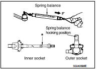
BALL JOINT SWINGING FORCE
• Hook a spring balance at the point shown in the figure and pull the spring balance. Make sure that the spring balance reads the specified value when ball stud and inner socket start to move. Replace outer socket or steering gear assembly (inner socket) if they are outside the standard.
Outer socket
(Measuring point of outer socket: Ball stud upper side)
: Refer to ST-23, "Socket Swing Force".
Inner socket
(Measuring point of inner socket: “*” mark shown in the
figure)
: Refer to ST-23, "Socket Swing Force".
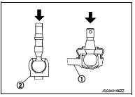
BALL JOINT AXIAL END PLAY
• Apply an axial load of 490 N (50 kg, 110 lb) to ball stud. Using a dial gauge, measure amount of stud movement, and then make sure that the value is within the following specified range. Replace outer socket (1) or steering gear assembly (inner socket) (2) if the measured value is outside the standard.
Outer socket : Refer to ST-24, "Socket Axial End Play".
Inner socket : Refer to ST-24, "Socket Axial End Play".
 Steering shaft
Exploded View
LHD models
1. Dash seal
2. Guide*
3. Intermediate shaft
: Vehicle front
: N·m (kg-m, ft-lb)
*: If reinstalling, this part is not required.
RHD models
1. Dash seal
2. Gu ...
 Service data and specifications (SDS)
General Specifications
Steering Wheel Axial End Play and Play
Steering Wheel Turning Force
Steering Angle
Steering Column Operating Range
*: For measuring position, refer to ST-11, &quo ...
Other materials:
Key switch
Component Function Check
1.CHECK FUNCTION
1. Select “DOOR LOCK” of “BCM” using CONSULT-III.
2. Select “KEY ON SW” in “DATA MONITOR” mode.
3. Check that the function operates normally according to the following
conditions.
Is the inspection result normal?
YES >> Key sw ...
ABS actuator and electric unit (control unit)
Exploded View
LHD
MR16DDT (2WD), HR16DE
1. ABS actuator and electric unit (control
unit)
2. ABS actuator and electric unit (control
unit) harness connector
3. Bracket
A. To front LH caliper
B. To rear RH caliper
C. To rear LH caliper
D. To front RH caliper
E. To master cylinder seco ...
B2268 water temp
Description
The engine coolant temperature signal is transmitted from ECM to the
combination meter via CAN communication.
DTC Logic
DTC DETECTION LOGIC
Diagnosis Procedure
1.PERFORM SELF-DIAGNOSIS OF ECM
Perform “Self Diagnosis Result” of “ENGINE”, and repair or replace
malfuncti ...
