Nissan Juke Service and Repair Manual : Steering shaft
Exploded View
LHD models
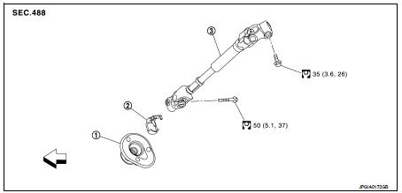
1. Dash seal
2. Guide*
3. Intermediate shaft
 : Vehicle front
 : N·m (kg-m, ft-lb)
*: If reinstalling, this part is not required.
RHD models
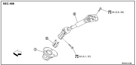
1. Dash seal 2. Guide* 3. Intermediate shaft
 : Vehicle front
 : N·m (kg-m, ft-lb)
*: If reinstalling, this part is not required.
Removal and Installation
REMOVAL
CAUTION:
Spiral cable may be cut if steering wheel turns while separating steering column
assembly and steering
gear assembly. Be sure to secure steering wheel using string to avoid turning.
1. Set vehicle to the straight-ahead position.
2. Place the tilt to the lowest level.
3. Remove instrument lower panel. Refer to IP-13, "Removal and Installation".
4. Remove intermediate shaft mounting bolt (steering gear side), and separate intermediate shaft from steering gear assembly.
CAUTION:
• Place a matching mark on both intermediate shaft and steering gear assembly
before removing
intermediate shaft.
• When removing intermediate shaft, never insert a tool, such as a screwdriver, into the yoke groove to pull out the intermediate shaft. In case of the violation of the above, replace intermediate shaft with a new one.
5. Remove intermediate shaft mounting bolt (steering column side), and remove intermediate shaft from steering column assembly.
CAUTION:
• Place a matching mark on both intermediate shaft and steering column assembly
before removing
intermediate shaft.
• When removing intermediate shaft, never insert a tool, such as a screwdriver, into the yoke groove to pull out the intermediate shaft. In case of the violation of the above, replace intermediate shaft with a new one.
6. Remove dash seal from vehicle.
7. Remove guide from intermediate shaft.
CAUTION:
Remove guide only when necessary.
8. Perform inspection after removal. Refer to ST-15, "Inspection".
INSTALLATION
CAUTION:
Spiral cable may be cut if steering wheel turns while separating steering column
assembly and steering
gear assembly. Be sure to secure steering wheel using string to avoid turning.
Note the following, and install in the reverse order of removal.
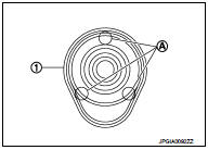
• To install dash seal (1) to the vehicle, insert dash seal into the steering gear assembly and press in the protrusions (A) by hand.
CAUTION:
Never allow dash seal lip to run off the engine room side or
passenger room side.
• Follow the instructions below to install intermediate shaft to steering gear assembly.
- Insert intermediate shaft into steering gear assembly. Align groove of the steering gear assembly with the bolt hole of the intermediate shaft.
CAUTION:
The guide protrusion is not required to be reinstalled.
- Check for galling while hand-tightening the mounting bolt of intermediate shaft (steering gear assembly side). After checking that the bolt is inserted in the groove of steering gear assembly, tighten the bolt to the specified torque.
• For intermediate shaft mounting bolt direction, refer to ST-13, "Exploded
View". (Do not insert it from the
other side.)
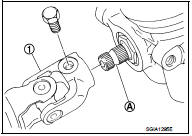
• When connecting intermediate shaft upper side (1) and column
shaft, make sure the bolt is securely seated in groove (A) of column
shaft (A) before final tightening.
• After installing steering column assembly, perform self-diagnosis with CONSULT-III to ensure correct operation. Refer to STC-10, "CONSULT-III Function".
• Perform inspection after installation. Refer to ST-15, "Inspection".
Inspection
INSPECTION AFTER REMOVAL
• Check each part of intermediate shaft for damage or other malfunctions. Replace if there are any abnormal conditions.
INSPECTION AFTER INSTALLATION
• Check each part of intermediate shaft for damage or other malfunctions. Replace if there are any abnormal conditions.
• Rotate steering wheel to check for decentered condition, binding, noise, or excessive steering effort.
• Check the steering wheel play, neutral position steering wheel, steering wheel turning force, and front wheel turning angle. Refer to ST-8, "Inspection", ST-5, "Inspection".
 Steering column
Exploded View
1. Cover
2. Sub-harness
3. Band
4. Steering column assembly
5. Slide plate (inner)
6. Slide plate (outer)
7. Bracket
Always replace after every
disassembly.
: N·m (kg- ...
 Steering gear and linkage
Exploded View
REMOVAL
LHD Models
1. Steering gear assembly
2. Heat insulator
3. Front suspension member
: Vehicle front
: Always replace after every
disassembly.
: N·m (kg-m, ft-lb)
: ...
Other materials:
Wiring diagram
SECURITY CONTROL SYSTEM
LHD
LHD : Wiring Diagram
For connector terminal arrangements, harness layouts, and alphabets in a
(option abbreviation; if not
described in wiring diagram), refer to GI-12, "Connector Information/Explanation
of Option Abbreviation".
RHD
RHD : Wiring D ...
ASCD main switch
Component Function Check
1.CHECK ASCD MAIN SWITCH FUNCTION
With CONSULT-III
1. Turn ignition switch ON.
2. Select “ENGINE” using CONSULT-III.
3. Select “MAIN SW” in “DATA MONITOR” mode.
4. Check “MAIN SW” indication under the following condition.
Without CONSULT-III
1. Turn ...
Diagnosis and repair work flow
Work Flow
OVERALL SEQUENCE
Reference 1··· Refer to AV-33, "MODELS WITH USB CONNECTION FUNCTION : Symptom
Table" (with USB
connection function) or AV-35, "MODELS WITHOUT USB CONNECTION FUNCTION : Symptom
Table" (without
USB connection function).
DETAILED FLOW
1.CH ...
