Nissan Juke Service and Repair Manual : ECU diagnosis information
ABS actuator and electric unit (control unit)
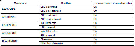
Reference Value
CONSULT-III DATA MONITOR STANDARD VALUE
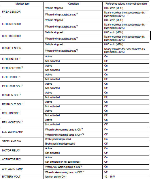
*1: Confirm tire pressure is standard value.
*2: Refer to “valve operation” in BRC-13, "System Description" for valve operation of each valve.
*3: Refer to BRC-13, "System Description" for ON/OFF conditions of each warning lamp and indicator lamp.
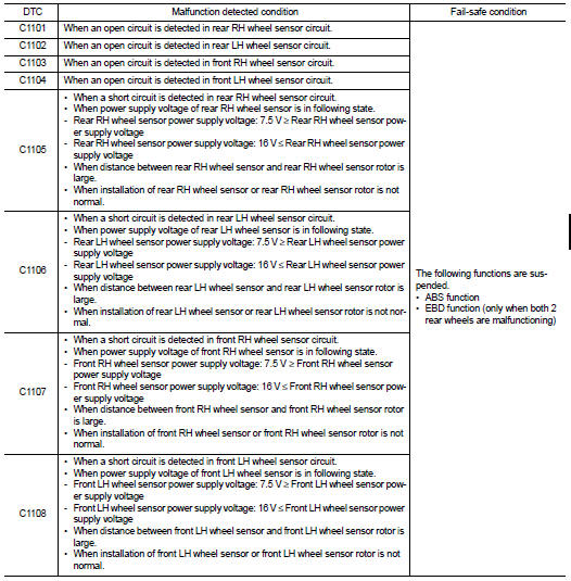
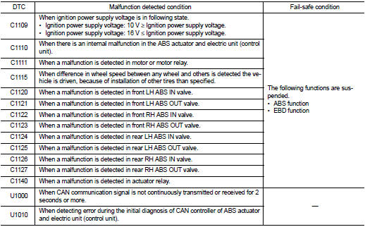
Fail-safe
ABS FUNCTION
ABS warning lamp in combination meter turn ON when a malfunction occurs in system [ABS actuator and electric unit (control unit)]. The control is suspended for ABS function. The vehicle status becomes the same as models without ABS function. However, EBD function is operated normally.
NOTE
:
ABS self-diagnosis sound may be heard the same as in the normal condition,
because self-diagnosis is performed
when ignition switch turns ON and when vehicle initially starts.
EBD FUNCTION
ABS warning lamp and brake warning lamp in combination meter turn ON when a malfunction occurs in system [ABS actuator and electric unit (control unit)]. The control is suspended for ABS function and EBD function.
The vehicle status becomes the same as models without ABS function and EBD function.
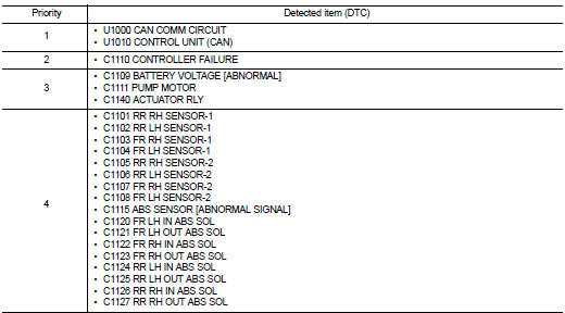
DTC Inspection Priority Chart
When multiple DTCs are displayed simultaneously, check one by one depending on the following priority list.
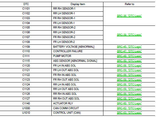
DTC Index
 Diagnosis system [ABS actuator and electric unit (control
unit)]
Diagnosis system [ABS actuator and electric unit (control
unit)]
CONSULT-III Function
APPLICATION ITEMS
CONSULT-III can display each diagnostic item using the diagnostic test modes
as follows.
*: The following diagnosis information is erased by erasing.
â ...
 Wiring diagram
BRAKE CONTROL SYSTEM
Wiring Diagram
For connector terminal arrangements, harness layout, and alphabets in a
(option abbreviation; if not
described in wiring diagram), refer to GI-12, "Connec ...
Other materials:
B1011, B1012, B1013, B1014, B1015 diagnosis sensor unit
DTC Logic
DTC DETECTION LOGIC
DTC CONFIRMATION PROCEDURE
1.CHECK SELF-DIAG RESULT
With CONSULT-III
1. Turn ignition switch ON.
2. Perform “Self Diagnostic Result” mode of “AIR BAG” using CONSULT-III.
Without CONSULT-III
1. Turn ignition switch ON.
2. Check the air bag warning la ...
P173B 1GR incorrect ratio
DTC Logic
DTC CONFIRMATION PROCEDURE
CAUTION:
• Be sure to perform “TM-445, "Diagnosis Procedure"” and then perform “DTC
CONFIRMATION PROCEDURE”.
• Never perform "DTC CONFIRMATION PROCEDURE" before the repairs. Doing so may
result in a secondary
malfunction.
...
Malfunction indicator
Component Function Check
1.CHECK MI FUNCTION
1. Turn ignition switch ON.
2. Make sure that MI lights up.
Is the inspection result normal?
YES >> INSPECTION END
NO >> Go to EC-1019, "Diagnosis Procedure".
Diagnosis Procedure
1.CHECK CAN COMMUNICATION LINE
Refer to LAN ...
