Nissan Juke Service and Repair Manual : Diagnosis system [ABS actuator and electric unit (control unit)]
CONSULT-III Function
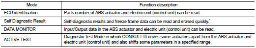
APPLICATION ITEMS
CONSULT-III can display each diagnostic item using the diagnostic test modes as follows.
*: The following diagnosis information is erased by erasing.
• DTC
• Freeze frame data (FFD)
ECU IDENTIFICATION
ABS actuator and electric unit (control unit) part number can be read.
SELF DIAGNOSTIC RESULT
Refer to BRC-31, "DTC Index".
When “CRNT” is displayed on self-diagnosis result • The system is presently malfunctioning.
When “PAST” is displayed on self-diagnosis result • System malfunction in the past is detected, but the system is presently normal.
Freeze frame data (FFD)
When DTC is detected, a vehicle state shown below is recorded and displayed on
CONSULT-III.
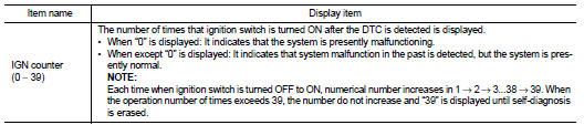
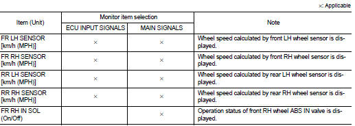
DATA MONITOR
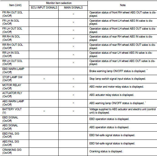
*: Refer to BRC-13, "System Description" for ON/OFF conditions of each warning lamp.
ACTIVE TEST
The active test is used to determine and identify details of a malfunction, based on self-diagnosis test result sand data obtained in the DATA MONITOR. In response to instructions from CONSULT-III, instead of those from ABS actuator and electric unit (control unit) on the vehicle, a drive signal is sent to the actuator to check its operation.
CAUTION:
• Never perform ACTIVE TEST while driving the vehicle.
• Always bleed air from brake system before ACTIVE TEST.
• Never perform ACTIVE TEST when system is malfunctioning.
NOTE:
• When active test is performed while depressing the pedal, the pedal depressing stroke may change. This is not a malfunction.
• “TEST IS STOPPED” is displayed approx. 10 seconds after operation start.
• When performing active test again after “TEST IS STOPPED” is displayed, select “BACK”.
• ABS warning lamp and brake warning lamp may turn ON during active test. This is not a malfunction.
ABS IN Valve and ABS OUT Valve When “Up”, “Keep” or “Down” is selected on display screen, the following items are displayed when system is normal.
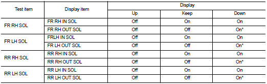
*: Immediately after being selected, status is “On”. Status changes to “Off” after approx. 2 seconds.
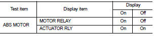
ABS Motor
When “On” or “Off” is selected on display screen, the following items are
displayed when system is normal.
 System
System Description
• The system switches fluid pressure of each brake caliper to increase, to
hold or to decrease according to
signals from control unit in ABS actuator and electric unit (contro ...
 ECU diagnosis information
ABS actuator and electric unit (control unit)
Reference Value
CONSULT-III DATA MONITOR STANDARD VALUE
*1: Confirm tire pressure is standard value.
*2: Refer to “valve operation” in BRC-13, ...
Other materials:
System
Body control system
BODY CONTROL SYSTEM : System Description
OUTLINE
• BCM (Body Control Module) controls the various electrical components. It
inputs the information required to
the control from CAN communication and the signal received from each switch and
sensor.
• BCM has combinatio ...
System operation
The system provides both visual and audible feedback regarding rearward obstacles whenever the shift lever is placed into the R (Reverse) position.
Sonar Operation Table
For safety and stability, the RSS is automatically deactivated when your speed exc ...
Cooler pipe and hose
Exploded View
1. A/C unit assembly
2. O-ring
3. High-pressure pipe
4. O-ring
5. Low-pressure flexible hose
6. High-pressure flexible hose
7. O-ring
8. Condenser
9. Compressor
: Do not reuse
: N·m (kg-m, in-lb)
: N·m (kg-m, ft-lb)
High-pressure flexible hose : Removal and Instal ...
