Nissan Juke Service and Repair Manual : Wiring diagram
BRAKE CONTROL SYSTEM
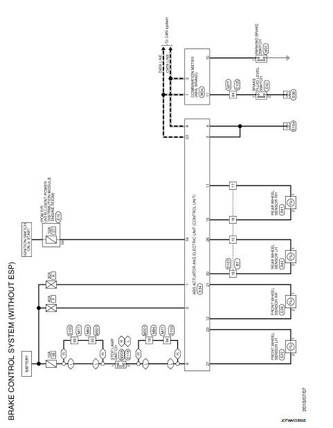
Wiring Diagram
For connector terminal arrangements, harness layout, and alphabets in a
 (option abbreviation; if not
described in wiring diagram), refer to GI-12, "Connector Information/Explanation
of Option Abbreviation".
 ECU diagnosis information
ABS actuator and electric unit (control unit)
Reference Value
CONSULT-III DATA MONITOR STANDARD VALUE
*1: Confirm tire pressure is standard value.
*2: Refer to “valve operation” in BRC-13, ...
 Basic inspection
Diagnosis and repair work flow
Work Flow
DETAILED FLOW
1.INTERVIEW FROM THE CUSTOMER
Clarify customer complaints before inspection. First of all, perform an
interview utilizing BRC-34, "Dia ...
Other materials:
P0826 up and down shift SW
DTC Logic
DTC DETECTION LOGIC
DTC CONFIRMATION PROCEDURE
CAUTION:
Always drive vehicle at a safe speed.
NOTE:
If “DTC CONFIRMATION PROCEDURE” has been previously conducted, always turn
ignition switch
OFF and wait at least 10 seconds before conducting the next test.
After the repai ...
P1572 ASCD brake switch
DTC Logic
DTC DETECTION LOGIC
NOTE:
• If DTC P1572 is displayed with DTC P0605, first perform the trouble diagnosis
for DTC P0605. Refer
to EC-683, "DTC Logic".
• This self-diagnosis has the one trip detection logic. When malfunction A is
detected, DTC is not
stored in ECM me ...
Diagnosis and repair workflow
Work Flow
OVERALL SEQUENCE
DETAILED FLOW
1.GET INFORMATION FOR SYMPTOM
Get the detailed information from the customer about the symptom (the
condition and the environment when
the incident/malfunction occurred) using the “Diagnostic Work Sheet”. (Refer to
EC-539, "Diagnostic Work ...
