Nissan Juke Service and Repair Manual : Basic inspection
Diagnosis and repair work flow
Work Flow
DETAILED FLOW
1.INTERVIEW FROM THE CUSTOMER
Clarify customer complaints before inspection. First of all, perform an interview utilizing BRC-34, "Diagnostic Work Sheet" and reproduce the symptom as well as fully understand it. Ask customer about his/her complaints carefully.Check symptoms by driving vehicle with customer, if necessary.
CAUTION:
Customers are not professional. Never guess easily like “maybe the customer
means that...,” or “
maybe the customer mentions this symptom”.
>> GO TO 2.
2.CHECK SYMPTOM
Reproduce the symptom that is indicated by the customer, based on the information from the customer obtained by interview. Also check that the symptom is not caused by fail-safe mode. Refer to BRC-19, "Failsafe".
CAUTION:
When the symptom is caused by normal operation, fully inspect each portion and
obtain the understanding
of customer that the symptom is not caused by a malfunction.
>> GO TO 3.
3.PERFORM THE SELF-DIAGNOSIS
 With CONSULT-III.
Perform self-diagnosis for “ABS”.
Is DTC detected? YES >> Record or print self-diagnosis results and GO TO 4.
NO >> GO TO 6. 4.RECHECK THE SYMPTOM
 With CONSULT-III.
1. Erase self-diagnostic results for “ABS”.
2. Perform DTC confirmation procedures for the error-detected system.
NOTE
:
If some DTCs are detected at the some time, determine the order for performing
the diagnosis based on
BRC-30, "DTC Inspection Priority Chart" [ABS actuator and electric unit (control
unit)].
Is any DTC detected? YES >> GO TO 5.
NO >> Check harness and connectors based on the information obtained by interview. Refer to GI-42, "Intermittent Incident".
5.REPAIR OR REPLACE ERROR-DETECTED PART
• Repair or replace error-detected parts.
• Reconnect part or connector after repairing or replacing.
• When DTC is detected, erase self-diagnostic result for “ABS”.
>> GO TO 7.
6.IDENTIFY ERROR-DETECTED SYSTEM BY SYMPTOM DIAGNOSIS
Estimate error-detected system based on symptom diagnosis and perform inspection.
Can the error-detected system be identified?
YES >> GO TO 7.
NO >> Check harness and connectors based on the information obtained by interview. Refer to GI-42, "Intermittent Incident".
7.FINAL CHECK
With CONSULT-III.
1. Check the reference value for “ABS”.
2. Recheck the symptom and check that the symptom is not reproduced on the same conditions.
Is the symptom reproduced? YES >> GO TO 3.
NO >> INSPECTION END
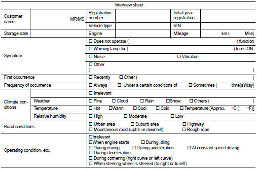
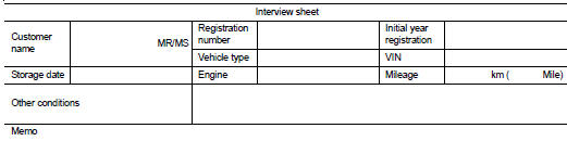
Diagnostic Work Sheet
Description
• In general, customers have their own criteria for a problem. Therefore, it is
important to understand the
symptom and status well enough by asking the customer about his/her concerns
carefully. To systemize all
the information for the diagnosis, prepare the interview sheet referring to the
interview points.
• In some cases, multiple conditions that appear simultaneously may cause a DTC to be detected.
INTERVIEW SHEET SAMPLE
 Wiring diagram
BRAKE CONTROL SYSTEM
Wiring Diagram
For connector terminal arrangements, harness layout, and alphabets in a
(option abbreviation; if not
described in wiring diagram), refer to GI-12, "Connec ...

Other materials:
Starting the EV system
1. Confirm that the electronic parking brake is fully applied and the brake indicator light is illuminated on the dashboard cluster.
2. Ensure and confirm that the vehicle transmission layout is securely locked in the P (Park) position before attempting initialization.
...
Sealant or/and Lubricant
HFC-134a (R-134a) Service Tool and Equipment
• Never mix HFC-134a (R-134a) refrigerant and/or its specified lubricant with
CFC-12 (R-12) refrigerant and/
or its lubricant.
• Separate and non-interchangeable service equipment must be used for handling
each type of refrigerant/
lubricant.
...
P2A00 A/F sensor 1
DTC Logic
DTC DETECTION LOGIC
To judge the malfunction, the A/F signal computed by ECM from the A/F sensor
1 signal is monitored so it will
not shift to LEAN side or RICH side.
DTC CONFIRMATION PROCEDURE
1.PRECONDITIONING
If DTC Confirmation Procedure has been previously conducted, always ...
