Nissan Juke Service and Repair Manual : IPDM-E branch line circuit
Diagnosis Procedure
1.CHECK CONNECTOR
1. Turn the ignition switch OFF.
2. Disconnect the battery cable from the negative terminal.
3. Check the terminals and connectors of the IPDM E/R for damage, bend and loose connection (unit side and connector side).
Is the inspection result normal? YES >> GO TO 2.
NO >> Repair the terminal and connector.
2.CHECK HARNESS FOR OPEN CIRCUIT
1. Disconnect the connector of IPDM E/R.
2. Check the resistance between the IPDM E/R harness connector terminals.
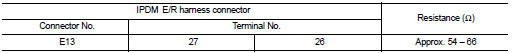
Is the measurement value within the specification? YES >> GO TO 3.
NO >> Repair the IPDM E/R branch line.
3.CHECK POWER SUPPLY AND GROUND CIRCUIT
Check the power supply and the ground circuit of the IPDM E/R. Refer to the following.
• Models with Intelligent Key system: PCS-33, "Diagnosis Procedure" • Models without Intelligent Key system: PCS-62, "Diagnosis Procedure"
Is the inspection result normal? YES (Present error)>>Replace the IPDM E/R. Refer to the following.
• Models with Intelligent Key system: PCS-34, "Removal and Installation" • Models without Intelligent Key system: PCS-63, "Removal and Installation"
YES (Past error)>>Error was detected in the IPDM E/R branch line.
NO >> Repair the power supply and the ground circuit.
 ABS branch line circuit
Diagnosis Procedure
1.CHECK CONNECTOR
1. Turn the ignition switch OFF.
2. Disconnect the battery cable from the negative terminal.
3. Check the terminals and connectors of the ABS actuator and ele ...
 TCM branch line circuit
Diagnosis Procedure
1.CHECK CONNECTOR
1. Turn the ignition switch OFF.
2. Disconnect the battery cable from the negative terminal.
3. Check the following terminals and connectors for damage, bend ...
Other materials:
Three-point type seat belt with retractor
WARNING
Every person who drives or rides in this vehicle should use a seat belt at all times to ensure maximum protection.
Never ride in a moving vehicle while the seatback is significantly reclined. This practice is inherently dangerous as the shoulder belt will not maintain ...
B1177 lap Pre-tensioner RH
DTC Logic
DTC CONFIRMATION PROCEDURE
1.CHECK SELF-DIAGNOSTIC RESULT
With CONSULT-III
1. Turn ignition switch ON.
2. Perform “Self Diagnostic Result” mode of “AIR BAG” using CONSULT-III.
Without CONSULT-III
1. Turn ignition switch ON.
2. Check the air bag warning lamp status. Refe ...
P0335 CKP sensor (POS)
DTC Logic
DTC DETECTION LOGIC
NOTE:
If DTC P0340 is displayed with DTC P0643, first perform the trouble diagnosis
for DTC P0643.
Refer to EC-307, "DTC Logic".
DTC CONFIRMATION PROCEDURE
1.PRECONDITIONING
If DTC Confirmation Procedure has been previously conducted, always perfo ...
