Nissan Juke Service and Repair Manual : TCM branch line circuit
Diagnosis Procedure
1.CHECK CONNECTOR
1. Turn the ignition switch OFF.
2. Disconnect the battery cable from the negative terminal.
3. Check the following terminals and connectors for damage, bend and loose connection (unit side and connector side).
- TCM
- Harness connecotor F1
- Harness connecotor E8
Is the inspection result normal? YES >> GO TO 2.
NO >> Repair the terminal and connector.
2.CHECK HARNESS FOR OPEN CIRCUIT
1. Disconnect the connector of TCM.
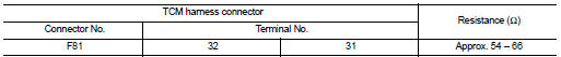
2. Check the resistance between the TCM harness connector terminals.
- HR16DE models

- MR16DDT models
Is the measurement value within the specification? YES >> GO TO 3.
NO >> Repair the TCM branch line.
3.CHECK POWER SUPPLY AND GROUND CIRCUIT
Check the power supply and the ground circuit of the TCM. Refer to the following.
ŌĆó HR16DE: TM-464, "Diagnosis Procedure" ŌĆó MR16DDT: TM-239, "Diagnosis Procedure"
Is the inspection result normal? YES (Present error)>>Replace the TCM. Refer to the following.
ŌĆó HR16DE: TM-490, "Removal and Installation" ŌĆó MR16DDT: TM-280, "Removal and Installation"
YES (Past error)>>Error was detected in the TCM branch line.
NO >> Repair the power supply and the ground circuit.
 IPDM-E branch line circuit
Diagnosis Procedure
1.CHECK CONNECTOR
1. Turn the ignition switch OFF.
2. Disconnect the battery cable from the negative terminal.
3. Check the terminals and connectors of the IPDM E/R for damage, ...
 DLC branch line circuit
Diagnosis Procedure
1.CHECK CONNECTOR
1. Turn the ignition switch OFF.
2. Disconnect the battery cable from the negative terminal.
3. Check the terminals and connectors of the data link connector ...
Other materials:
Service information for electrical incident
Work Flow
WORK FLOW
Control Units and Electrical Parts
PRECAUTIONS
ŌĆó Never reverse polarity of battery terminals.
ŌĆó Install only parts specified for a vehicle.
ŌĆó Before replacing the control unit, check the input and output and functions of
the component parts.
ŌĆó Do not apply ex ...
Rear door finisher
Exploded View
1. Rear door panel
2. Grommet
3. Rear door corner cover inner
4. Cap
5. Power window switch finisher
6. Rear door finisher
: Clip
: Pawl
: Metal clip
Removal and Installation
REMOVAL
CAUTION:
ŌĆó When removing, always use a remover tool that is made of plastic.
ŌĆó ...
Precaution Necessary for Steering Wheel Rotation after Battery Disconnect
NOTE:
ŌĆó Before removing and installing any control units, first turn the ignition
switch to the LOCK position, then disconnect
both battery cables.
ŌĆó After finishing work, confirm that all control unit connectors are connected
properly, then re-connect both
battery cables.
ŌĆó Always us ...
