Nissan Juke Service and Repair Manual : DLC branch line circuit
Diagnosis Procedure
1.CHECK CONNECTOR
1. Turn the ignition switch OFF.
2. Disconnect the battery cable from the negative terminal.
3. Check the terminals and connectors of the data link connector for damage, bend and loose connection (connector side and harness side).
Is the inspection result normal? YES >> GO TO 2.
NO >> Repair the terminal and connector.
2.CHECK HARNESS FOR OPEN CIRCUIT
Check the resistance between the data link connector terminals.
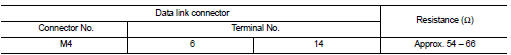
Is the measurement value within the specification? YES (Present error)>>Check CAN system type decision again.
YES (Past error)>>Error was detected in the data link connector branch line circuit.
NO >> Repair the data link connector branch line.
 TCM branch line circuit
Diagnosis Procedure
1.CHECK CONNECTOR
1. Turn the ignition switch OFF.
2. Disconnect the battery cable from the negative terminal.
3. Check the following terminals and connectors for damage, bend ...
 EPS branch line circuit
Diagnosis Procedure
1.CHECK CONNECTOR
1. Turn the ignition switch OFF.
2. Disconnect the battery cable from the negative terminal.
3. Check the terminals and connectors of the EPS control unit for ...
Other materials:
Diagnosis and repair work flow
Work Flow
OVERALL SEQUENCE
DETAILED FLOW
1.GET INFORMATION FOR SYMPTOM
1. Get the detailed information from the customer about the symptom (the
condition and the environment
when the incident/malfunction occurred).
2. Check operation condition of the function that is malfunctioning.
> ...
P1585 G sensor
Description
• G sensor is installed to floor under instrument lower cover.
• G sensor detects longitudinal G and inclination that affects the vehicle and
outputs to ECM using analog voltage.
ECM converts the analog voltage value to digital signal and transmits the signal
to TCM via CAN ...
Security systems
To provide comprehensive protection, your Nissan Leaf is equipped with two distinct security systems designed to safeguard your vehicle:
Vehicle security system
NISSAN Vehicle Immobilizer System
The current operational status of these systems ...
