Nissan Juke Service and Repair Manual : ABS branch line circuit
Diagnosis Procedure
1.CHECK CONNECTOR
1. Turn the ignition switch OFF.
2. Disconnect the battery cable from the negative terminal.
3. Check the terminals and connectors of the ABS actuator and electric unit (control unit) for damage, bend and loose connection (unit side and connector side).
Is the inspection result normal? YES >> GO TO 2.
NO >> Repair the terminal and connector.
2.CHECK HARNESS FOR OPEN CIRCUIT
1. Disconnect the connector of ABS actuator and electric unit (control unit).
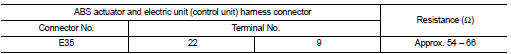
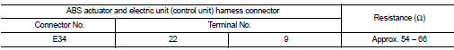
2. Check the resistance between the ABS actuator and electric unit (control unit) harness connector terminals.
- Models with ESP
- Models without ESP
Is the measurement value within the specification? YES >> GO TO 3.
NO >> Repair the ABS actuator and electric unit (control unit) branch line.
3.CHECK POWER SUPPLY AND GROUND CIRCUIT
Check the power supply and the ground circuit of the ABS actuator and electric unit (control unit). Refer to the following.
• Models without ESP: BRC-64, "Diagnosis Procedure" • Models with ESP: BRC-205, "Diagnosis Procedure"
Is the inspection result normal? YES (Present error)>>Replace the ABS actuator and electric unit (control unit). Refer to the following.
• Models without ESP: BRC-90, "Removal and Installation".
• Models with ESP: BRC-233, "Removal and Installation".
YES (Past error)>>Error was detected in the ABS actuator and electric unit (control unit) branch line.
NO >> Repair the power supply and the ground circuit.
 4WD branch line circuit
Diagnosis Procedure
1.CHECK CONNECTOR
1. Turn the ignition switch OFF.
2. Disconnect the battery cable from the negative terminal.
3. Check the following terminals and connectors for damage, bend ...
 IPDM-E branch line circuit
Diagnosis Procedure
1.CHECK CONNECTOR
1. Turn the ignition switch OFF.
2. Disconnect the battery cable from the negative terminal.
3. Check the terminals and connectors of the IPDM E/R for damage, ...
Other materials:
Illumination
Wiring Diagram
For connector terminal arrangements, harness layouts, and alphabets in a
(option abbreviation: if not
described in wiring diagram), refer to GI-12, "Connector Information/Explanation
of Option Abbreviation".
...
Engine oil
Inspection
ENGINE OIL LEVEL
NOTE:
Before starting engine, put vehicle horizontally and check the engine oil level.
If engine is already started, stop
it and allow 10 minutes before checking.
1. Pull out oil level gauge and wipe it clean.
2. Insert oil level gauge and check that the engine ...
CD/USB memory care and cleaning
CD
• Handle a CD by its edges. Never touch the surface of the disc. Do not bend
the disc.
• Always place the discs in the storage case when they are not being used.
• To clean a disc, wipe the surface from the center to the outer edge using a clean,
soft cloth. Do not wipe the d ...
