Nissan Juke Service and Repair Manual : Front fender
Exploded View
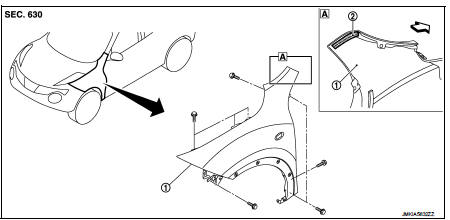
1. Front fender assembly 2. Front fender stiffener
 : Vehicle front
Removal and Installation
REMOVAL
1. Remove front fillet molding. Refer to EXT-26, "FRONT FILLET MOLDING : Removal and Installation".
2. Remove front bumper fascia assembly. Refer to EXT-13, "Removal and Installation".
3. Remove sill cover. Refer to EXT-23, "Removal and Installation".
4. Remove fender protector. Refer to EXT-22, "Removal and Installation".
5. Remove front fender cover. Refer to EXT-20, "Exploded View".
6. Remove front combination lamp. Refer to EXL-91, "Removal and Installation".
7. Remove side turn signal lamp. Refer to EXL-98, "Removal and Installation".
8. Remove mounting bolts of front fender assembly.
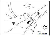
9. Remove front fender stiffener (2) from the vehicle body while carefully pulling upper portion of front fender (1) toward vehicle outside.
 : Vehicle front
10. Remove front fender assembly.
CAUTION:
An viscous urethane foam is installed on the back surface of front fender. When
removing the
front fender, be careful to not deform the front fender while performing the
procedure and removing
the viscous urethane foam a little at a time.
INSTALLATION
Note the following items, and install in the reverse order of removal.
CAUTION:
• After installation, apply the touch-up paint (the body color) onto the head of
front fender mounting
bolts.
• After installation, adjust the following part.
- Hood assembly: Refer to DLK-440, "HOOD ASSEMBLY : Adjustment".
- Front door: Refer to DLK-454, "DOOR ASSEMBLY : Adjustment".
 Radiator core support
HR16DE
HR16DE : Exploded View
1. Radiator core support upper
2. Air guide RH (MT models)
3. Radiator core support lower
4. Air guide LH
5. Air guide (upper)
6. Air guide LH (CVT models)
...
 Front door
Exploded View
1. Front door panel
2. Grommet
3. Door hinge (upper)
4. Door hinge (lower)
5. Door check link
6. Bumper rubber
7. Door pad
8. Door striker
9. TORX bolt
10. Grommet
: D ...
Other materials:
Diagnosis system (BCM) (with intelligent key system)
Common item
COMMON ITEM : CONSULT-III Function (BCM - COMMON ITEM)
APPLICATION ITEM
CONSULT-III performs the following functions via CAN communication with BCM.
SYSTEM APPLICATION
BCM can perform the following functions for each system.
NOTE:
It can perform the diagnosis modes except the fo ...
Diagnosis system (IPDM E/R)
Diagnosis Description
AUTO ACTIVE TEST
Description
In auto active test mode, the IPDM E/R sends a drive signal to the following
systems to check their operation.
• Oil pressure warning lamp (only for K9K engine models)
• Rear window defogger
• Front wiper motor
• Parking lamp
• ...
Engine overheating
Description
CHART 17: ENGINE OVERHEATING
Diagnosis Procedure
1.CHECK COOLING SYSTEM
Check the cooling system. Refer to CO-60, "Troubleshooting Chart".
Is the inspection result normal?
YES >> GO TO 2.
NO >> Repair or replace.
2.CHECK ECM POWER SUPPLY AND GROUND CIR ...
