Nissan Juke Service and Repair Manual : Removal and Installation
REMOVAL
1. Shift the transaxle to the neutral position, and then release the parking brake.
2. Put matching marks on propeller shaft flange yoke and final drive companion flanges.
CAUTION:
For matching marks, use paint. Never damage propeller shaft flange yoke and
final drive companion
flange.
3. Put matching marks on propeller shaft flange yoke and transfer companion flanges.
CAUTION:
For matching marks, use paint. Never damage propeller shaft flange yoke and
transfer companion
flange.
4. Loosen mounting nuts of center bearing mounting bracket.
NOTE
:
Tighten mounting nuts temporarily.
5. Remove propeller shaft assembly fixing bolts and nuts.
6. Remove center bearing mounting bracket fixing nuts.
7. Remove propeller shaft assembly.
CAUTION:
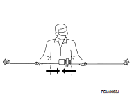
• This procedure requires 2 workers. Constant velocity joint must be handled
with care.
• If constant velocity joint was bent during propeller shaft assembly removal, installation, or transportation, its boot (1) may be damaged. Wrap boot interference area to metal part (2) with shop cloth or rubber to protect boot from breakage.
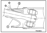
• Since no retaining pin is included in sliding direction, the boot may be damaged or dropped if the constant velocity joint is slid out 25 mm (0.98 in) or more from the original length. Therefore, handle constant velocity joint by sliding it inward.
8. Perform inspection after removal. Refer to DLN-123, "Inspection".
INSTALLATION
Note the following, and install in the reverse order of removal.
• Align matching marks to install propeller shaft assembly to final drive and transfer companion flanges.
• To install, adjust front and rear position of mount bracket to avoid deflection (front-rear direction of the vehicle) to the center bearing insulator.
• Perform inspection after installation. Refer to DLN-123, "Inspection".
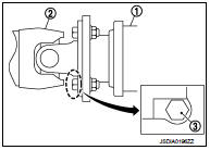
• After tightening the bolts and nuts to the specification torque, check that the bolts (3) on the flange side is tightened as shown in the figure.
1. Final drive assembly 2. Propeller shaft assembly
• If propeller shaft assembly or final drive assembly has been replaced,
connect them as follows:
CAUTION:
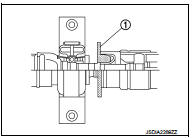
Constant velocity joint of a new propeller shaft has a preinstalled
protector (1). Protector must be removed after
installing propeller shaft.
1. Install propeller shaft (1) while aligning its matching mark (A) of propeller shaft with the matching mark (B) of final drive (2) on the joint as close as possible.
2. Temporary tighten bolts and nuts.
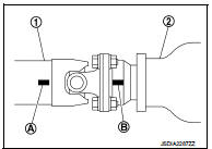
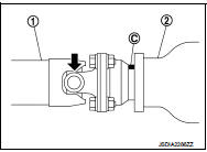
3. Press down propeller shaft (1) with matching mark (C) of final drive (2) facing upward. Then tighten fixing bolts and nuts to the specified torque.
 Exploded View
1. Propeller shaft assembly
: Vehicle front
: N·m (kg-m, ft-lb)
: Always replace after every
disassem ...
 Inspection
INSPECTION AFTER REMOVAL
Appearance
Check the propeller shaft for bend and damage. If damage is detected, replace
propeller shaft assembly.
Propeller Shaft Runout
Check propeller shaft runout ...
Other materials:
Drive information
While in the Drive mode, push the Drive information button to display elapsed
time, average speed and trip distance. Pressing the Drive information button a second
time will display the G (gravity)-Force screen.
Elapsed time
The elapsed time shows the time since the last reset.
Average spee ...
Intelligent key
Component Function Check
1.CHECK FUNCTION
1. Select “INTELLIGENT KEY” of “BCM” using CONSULT-III.
2. Select “RKE OPE COUN1” in “DATA MONITOR” mode.
3. Check that the function operates normally according to the following
conditions.
Is the inspection result normal?
YES >& ...
Component parts
Component Parts Location
1. BCM
Refer to BCS-6, "BODY CONTROL
SYSTEM : Component Parts Location"
(with Intelligent Key) or BCS-96,
"BODY CONTROL SYSTEM : Component
Parts Location" (without Intelligent
Key)
2. Power window main switch
3. Front power window motor (drive ...
