Nissan Juke Service and Repair Manual : Inspection
INSPECTION AFTER REMOVAL
Appearance
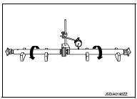
Check the propeller shaft for bend and damage. If damage is detected, replace
propeller shaft assembly.
Propeller Shaft Runout
Check propeller shaft runout at measuring points with a dial indicator.
If runout exceeds specifications, replace propeller shaft assembly.
Propeller shaft runout : Refer to DLN-125, "Propeller Shaft Runout".
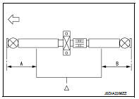
• Propeller shaft runout measuring point (Point “
”)
 : Front
Dimension A: 542 mm (21.34 in) B: 516.5 mm (20.33 in)
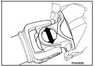
Journal Axial Play
As shown in the figure, while fixing yoke on one side, check axial
play of joint. If it is outside the standard, replace propeller shaft
assembly.
Journal axial play : Refer to DLN-125, "Journal Axial Play".
CAUTION:
Never disassemble joints.
Center Bearing
Check center bearing for noise and damage. If noise or damage is detected,
replace propeller shaft assembly.
CAUTION:
Never disassemble center bearing.
INSPECTION AFTER INSTALLATION
After assembly, perform a driving test to check propeller shaft vibration. If vibration occurred, separate propeller shaft from final drive or transfer. Reinstall companion flange by changing the phase between companion flange and propeller shaft by the one bolt hole at a time. Then perform driving test and check propeller shaft vibration again at each point.
 Removal and Installation
REMOVAL
1. Shift the transaxle to the neutral position, and then release the parking
brake.
2. Put matching marks on propeller shaft flange yoke and final drive companion
flanges.
CAUTION:
F ...

Other materials:
Valve oil seal
VALVE OIL SEAL : Removal and Installation
REMOVAL
1. Remove camshafts. Refer to EM-78, "Exploded View".
2. Remove valve lifters. Refer to EM-78, "Exploded View".
3. Rotate crankshaft, and set piston whose valve oil seal is to be removed to
TDC. This will prevent valve
from ...
U0141 lost communication (BCM A)
Description
CAN (Controller Area Network) is a serial communication line for real-time
application. It is an on-vehicle multiplex
communication line with high data communication speed and excellent malfunction
detection ability.
Many electronic control units are equipped onto a vehicle, and ...
B1036 crash zone sensor
DTC Logic
DTC DETECTION LOGIC
DTC CONFIRMATION PROCEDURE
1.CHECK SELF-DIAG RESULT
With CONSULT-III
1. Turn ignition switch ON.
2. Perform “Self Diagnostic Result” mode of “AIR BAG” using CONSULT-III.
Without CONSULT-III
1. Turn ignition switch ON.
2. Check the air bag warning la ...
