Nissan Juke Service and Repair Manual : Parking brake system
Inspection and Adjustment
INSPECTION
Lever Stroke
1. Operate the parking brake lever with a force of 196 N (20 kg, 44 lb). Check
that the lever stroke is within
the specified number of notches. (Check it by listening to the clicks of the
ratchet.)
Number of notches : Refer to PB-11, "Parking Brake Control".
2. When parking brake warning lamp turns ON, check that the lever stroke is within the specified number of notches. (Check it by listening to the clicks of the ratchet.)
Number of notches : Refer to PB-11, "Parking Brake Control".
Inspect Components
• Check each component for installation condition such as looseness.
• Check the parking brake lever assembly for bend, damage and cracks. Replace if necessary.
• Check the cables and equalizer for wear, damage and cracks. Replace if necessary.
• Check the parking brake switch, and replace it if necessary. Refer to BRC-70, "Component Inspection" (without ESP), BRC-208, "Component Inspection" (with ESP).
ADJUSTMENT
1. Remove rear tires.
2. Fix the disc rotor using wheel nut.
3. Remove the console mask. Refer to IP-22, "Exploded View".
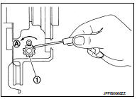
4. Remove the adjusting hole plug from the disc rotor. Turn the adjuster (1) in the direction (A) as shown in the figure using a suitable tool until the disc rotor is locked.
5. Turn back the adjuster 7 notches from the locked position.
6. Rotate the disc rotor to check that there is no drag. Install the adjuster hole plug. Refer to PB-9, "Inspection and Adjustment".
7. Adjust the cable with the following procedure.
a. Operate and maintain the parking brake lever with a force of 400 N (41 kg, 90 lb) for 15 minutes or more.
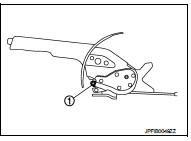
b. Adjust the parking brake lever stroke by turning the adjusting nut (1) with a socket wrench.
CAUTION:
Make sure to securely depress the brake pedal.
c. Operate the parking brake lever with a force of 196 N (20 kg, 44lb). Check that the lever stroke is within the specified number of notches. (Check it by listening to the clicks of the ratchet.)
Number of notches : Refer to PB-11, "Parking Brake Control".
d. Rotate the disc rotor to check that there is no drag. Refer to PB- 9, "Inspection and Adjustment".

 Parking brake shoe
Adjustment
1. Adjust parking brake lever stroke. Refer to PB-2, "Inspection and
Adjustment".
2. Perform parking brake break-in (drag on) operation by driving vehicle under
the followin ...
Other materials:
Outside key antenna
Driver side
DRIVER SIDE : Removal and Installation
REMOVAL
Remove the driver side outside handle. Refer to DLK-176, "OUTSIDE HANDLE :
Removal and Installation".
INSTALLATION
Install in the reverse order of removal.
Passenger side
PASSENGER SIDE : Removal and Installation
REMOVA ...
P183D side G sensor
DTC Logic
DTC DETECTION LOGIC
DTC CONFIRMATION PROCEDURE
1.PRECONDITIONING
If “DTC CONFIRMATION PROCEDURE” has been previously conducted, always turn
ignition switch OFF and
wait at least 10 seconds before conducting the next test.
>> GO TO 2.
2.DTC REPRODUCTION PROCEDURE
W ...
Service
• Disconnect battery negative terminal in advance.
• Disconnect air bag system line in advance.
• Never tamper with or force air bag lid open, as this may adversely affect air
bag performance.
• Be careful not to scratch pad and other parts.
• When removing or disassembling any par ...
