Nissan Juke Service and Repair Manual : Front door
Exploded View
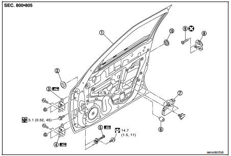
1. Front door panel
2. Grommet
3. Door hinge (upper)
4. Door hinge (lower)
5. Door check link
6. Bumper rubber
7. Door pad
8. Door striker
9. TORX bolt
10. Grommet
 : Do not reuse
 : N┬Ęm (kg-m, in-lb)
 : N┬Ęm (kg-m, ft-lb)
 : Body grease
Door assembly
DOOR ASSEMBLY : Removal and Installation
CAUTION:
ŌĆó Perform work with 2 workers, because of its heavy weight.
ŌĆó When removing and installing front door assembly, support door with a jack and shop cloth to protect door and body.
REMOVAL
1. Disconnect front door harness connector.
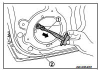
2. Remove mounting bolt of door check link on the vehicle.
3. Remove door hinge mounting bolts (door side), and then remove door assembly.
INSTALLATION
Note the following items, and install in the reverse order of removal.
CAUTION:
ŌĆó Apply anticorrosive agent onto the mounting surface.
ŌĆó Check front door open/close, lock/unlock operation after installation.
ŌĆó Check door hinge rotating part for poor lubrication. If necessary, apply body grease.
ŌĆó After installation, perform the fitting adjustment. Refer to DLK-454, "DOOR ASSEMBLY : Adjustment".
ŌĆó After installation, apply touch-up paint (the body color) onto the head of door hinge mounting nuts.
DOOR ASSEMBLY : Adjustment
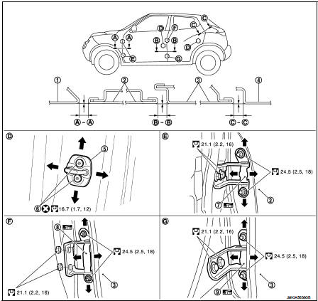
1. Front fender
2. Front door
3. Rear door
4. Body side outer
5. Door striker
6. TORX bolt
7. Front door hinge
8. Rear door hinge (upper)
9. Rear door hinge (lower)
 : Do not reuse
 : N┬Ęm (kg-m, ft-lb)
 : Body grease
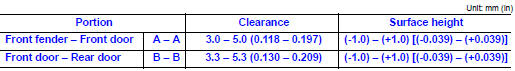
Check the clearance and surface height between front door and each part by visually and touching.
If the clearance and the surface height are out of specification, adjust them according to the procedures shown below.
FITTING ADJUSTMENT PROCEDURE
1. Remove front fender. Refer to DLK-450, "Removal and Installation".
2. Loosen door hinge mounting nuts on door side.
3. Adjust the surface height of front door according to the fitting standard dimension.
4. Temporarily tighten door hinge mounting nuts on door side.
5. Loosen door hinge mounting bolts on body side.
6. Raise front door at rear end to adjust clearance of the front door according to the fitting standard dimension.
7. After adjustment tighten bolts and nuts to the specified torque.
CAUTION:
ŌĆó After installation, apply touch-up paint (the body color) onto the head of
hinge mounting bolts
and nuts.
ŌĆó Check door hinge rotating part for poor lubrication. If necessary, apply body grease.
8. Install front fender. Refer to refer to DLK-450, "Removal and Installation".
DOOR STRIKER ADJUSTMENT
Adjust door striker so that it becomes parallel with door lock insertion direction.
Door striker
DOOR STRIKER : Removal and Installation
REMOVAL
Remove TORX bolts, and then remove door striker.
INSTALLATION
Note the following items, and install in the reverse order of removal.
CAUTION:
ŌĆó Check front door open/close, lock/unlock operation after installation.
ŌĆó After installation, be sure to perform the fitting adjustment. Refer to DLK-454, "DOOR ASSEMBLY : Adjustment".
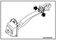
Door hinge
DOOR HINGE : Removal and Installation
REMOVAL
CAUTION:
ŌĆó Perform work with 2 workers, because of its heavy weight.
ŌĆó When removing and installing front door assembly, support door with a jack and shop cloth to protect door and body.
1. Remove front fender. Refer to DLK-450, "Removal and Installation".
2. Remove front door assembly. Refer to DLK-452, "DOOR ASSEMBLY : Removal and Installation".
3. Remove front door hinge mounting bolts (body side), and then remove front door hinge.
INSTALLATION
Note the following items, and install in the reverse order of removal.
CAUTION:
ŌĆó Apply anticorrosive agent onto the mounting surface.
ŌĆó Check front door open/close, lock/unlock operation after installation.
ŌĆó After installation, perform the fitting adjustment. Refer to DLK-454, "DOOR ASSEMBLY : Adjustment".
ŌĆó After installation, apply touch-up paint (the body color) onto the head of door hinge mounting nuts.
ŌĆó Check door hinge rotating part for poor lubrication. If necessary, apply body grease.
 : Grease up point
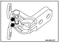
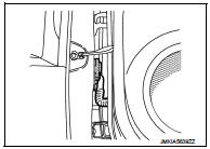
Door check link
DOOR CHECK LINK : Removal and Installation
REMOVAL
1. Fully close the front door window.
2. Remove front door finisher. Refer to INT-13, "Removal and Installation".
3. Disconnect harness connector of front door speaker.
4. Remove mounting bolts of front door speaker, and then remove front door speaker.
5. Remove mounting bolt of door check link on the vehicle.
6. Remove mounting bolts of door check link on door panel.
7. Take door check link (1) out from the hole of door panel (2).
INSTALLATION
Note the following item, and install in the reverse order of removal.
CAUTION:
ŌĆó Check front door open/close operation after installation.
ŌĆó Check door check link rotating part for poor lubrication. If necessary, apply grease.
 : Grease up point
 Front fender
Exploded View
1. Front fender assembly
2. Front fender stiffener
: Vehicle front
Removal and Installation
REMOVAL
1. Remove front fillet molding. Refer to EXT-26, "FRONT FILLET MOLDING : ...
 Rear door
Exploded View
1. Rear door panel
2. Door hinge (upper)
3. Door hinge (lower)
4. Door check link
5. Door striker
6. TORX bolt
: Do not reuse
: N┬Ęm (kg-m, in-lb)
N┬Ęm (kg-m, ft-lb)
: B ...
Other materials:
Diagnosis and repair workflow
Work Flow
OVERALL SEQUENCE
ŌĆó Malfunctions are declared as either present or stored (depending on whether
they appeared in a certain context
and have disappeared since, or whether they remain present but have not been
diagnosed within the
current context).
ŌĆó The present or stored statu ...
Rear door
Exploded View
1. Rear door panel
2. TORX bolt
3. Door striker
4. Door check link
5. Door hinge (lower)
6. Door hinge (upper)
: Do not reuse
: N┬Ęm (kg-m, in-lb)
: N┬Ęm (kg-m, ft-lb)
: Body grease
Door assembly
DOOR ASSEMBLY : Removal and Installation
CAUTION:
ŌĆó Perform work wit ...
4WD warning lamp does not turn off
Description
4WD warning lamp does not turn OFF several seconds after the engine started.
Diagnosis Procedure
1.PERFORM SELF-DIAGNOSIS
With CONSULT-III
Perform self-diagnosis for ŌĆ£ALL MODE AWD/4WDŌĆØ.
Is any DTC detected?
YES >> Check the DTC. Refer to DLN-33, "DTC Index".
...
