Nissan Juke Service and Repair Manual : Diagnosis and repair workflow
Work Flow
OVERALL SEQUENCE
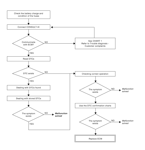
• Malfunctions are declared as either present or stored (depending on whether they appeared in a certain context and have disappeared since, or whether they remain present but have not been diagnosed within the current context).
• The present or stored status of malfunctions should be taken into consideration when the diagnostic tool is used following the + after ignition supply being switched on (without acting on the system components).
• For a present malfunction, apply the procedure described in the Interpretation of malfunction section.
• For a stored malfunction, note the malfunctions displayed and apply the instructions in the Notes section.
• If the malfunction is confirmed when the instructions in the Notes section are applied, the malfunction is present. Deal with the malfunction • If the malfunction is not confirmed, check: - the electrical lines which correspond to the malfunction, - the connectors for these lines (for oxidation, bent pins, etc), - the condition of the wires (insulation has melted or been cut, abrasions), - the resistance of the component detected as malfunction.
Conformity Check
• The aim of the conformity check is to check data that does not produce a
malfunction on the diagnostic tool
because the data is inconsistent. Therefore, this phase is used to:
- carry out malfunction finding on malfunctions that do not have a malfunction
display, and which may correspond
to a customer complaint.
- check that the system is operating correctly and that there is no risk of a malfunction recurring after repairs.
• This section gives the malfunction finding procedures for statuses and parameters and the conditions for checking them.
• If a status is not behaving normally or a parameter is outside the permitted tolerance values, consult the corresponding malfunction finding page.
Customer Complaints - Malfunction finding chart If the test with the diagnostic tool is OK but the customer complaint is still present, the malfunction should be processed by customer complaint.
NOTE
:
A synopsis of the general procedure to follow is provided on the preceding page
in the form of a flow
chart.
Malfunction Finding Procedure (Wiring Check) Diagnostics malfunctions Removing the connectors and/or handling the wirings may temporarily remove the origin of a DTC. The measurements of the electrical voltages, resistance and insulation are generally correct, especially when the DTC is not present at the time of the analysis (stored DTC).
Visual Check
Look for impacts under the bonnet and in the passenger compartment.
Perform a careful check of the protections, insulation and correct running of wirings.
Look for traces of oxidation.
Tactile Check
While manipulating the wirings, use the diagnostic tool to detect a change in
DTC status from ???stored??? to
???present???.
Ensure that the connectors are correctly engaged.
Apply light stresses to the connectors.
Gently manipulate the wiring harness.
If a change of status occurs, try to isolate the origin of the incident.
Inspection of each component Disconnect the connectors and check the appearance of the clips and blades and their crimping (no crimping on the insulating part).
Check that the clips and blades are properly engaged in the receptacles.
Ensure that there is no rebounding of clips or blades at the time of connection.
Check the contact pressure of the clips using a suitable model blade.
Resistance Control
Test the continuity of the lines in their entirety, then section by section.
Try to create a short-circuit to earth, on the + 12 V or with another wire.
If a DTC is detected, repair or replace the wiring.
REMINDERS
Trouble Diagnosis:
There are present DTCs and stored DTCs (which appeared in a certain context and have since disappeared or which are still present but have not had trouble diagnosis performed on them in the current context).
The ???present??? or ???stored??? status of DTCs must be considered when activating the diagnostic tool after power is supplied to the ECM (without activating the system components).
Deal with present DTCs according to the procedure specified in the corresponding DTC trouble diagnosis.
For stored DTCs, note the DTCs displayed and follow the instructions in the Notes section.
If the DTC is confirmed when the instructions in the Notes section are applied, the malfunction is present. Deal with the DTC.
If the DTC is not confirmed, check: • Electrical lines which correspond to the malfunction • Connectors for these lines (for oxidation, bent pins, etc.) • Resistance of the malfunction component • Condition of the wires (melted or cut insulation, wear)
Conformity Check
The conformity check is designed to check the states and data monitor items
which do not display any DTCs
on the diagnostic tool when inconsistent. This phase therefore allows:
• Diagnoses malfunctions that do not have a DTC display, and which may
correspond to a customer complaint.
• Checks that the system is operating correctly and that there is no risk of a DTC reappearing after repairs.
This section gives the trouble diagnosis procedures for states and parameters and the conditions for checking them.
If a state is not operating normally or a data monitor value is outside permitted tolerance values, you should consult the corresponding trouble diagnosis page.
Customer Complaints - Trouble Diagnosis If the test with the CONSULT-III is OK, but the customer complaint still present, the malfunction should be treated by customer complaints.
A synopsis of the general procedure to follow is provided on the previous page in the form of a flow chart.
SAFETY ADVICE
• The safety instructions must be followed at all times when working on
components, to avoid damage or
injury:
- make sure that the battery is properly charged to avoid damaging the computers
with a low load,
- use the appropriate tools,
- do not touch the xenon bulbs.
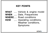
Diagnostic Work Sheet
DESCRIPTION
There are many operating conditions that lead to the malfunction of engine components. A good grasp of such conditions can make troubleshooting faster and more accurate.
In general, each customer feels differently about a incident. It is important to fully understand the symptoms or conditions for a customer complaint.
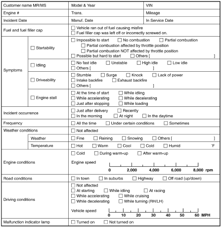
Utilize a diagnostic worksheet like the one on the next page in order to organize all the information for troubleshooting.
Some conditions may cause the MI to come on steady or blink and DTC to be detected. Examples: • Vehicle ran out of fuel, which caused the engine to misfire.
• Fuel filler cap was left off or incorrectly screwed on, allowing fuel to evaporate into the atmosphere.
WORKSHEET SAMPLE
 Basic inspection
...
 Basic inspection
Description
NOTE:
Only consult the tests after following the diagnostic procedure chart.
Some specific checks are grouped under the ???tests??? heading and are used as
required in different dia ...
Other materials:
Ignition coil, spark plug and rocker cover
Exploded View
1. Rocker cover protector
2. O-ring
3. PCV control valve
4. PCV hose
5. Clamp
6. Rocker cover gasket
7. Rocker cover
8. Clamp
9. PCV hose
10. Oil filler cap
11. Spark plug
12. Ignition coil
A. To air duct assembly
B.Tightening must be done following
the instal ...
Thermostat
Inspection
• Place a thread so that it is caught in the valves of the thermostat.
Immerse fully in a container filled with water. Heat while stirring.
(The example in the figure shows the thermostat.)
• The valve opening temperature is the temperature at which the
valve opens and falls ...
P0031, P0032 A/F sensor 1 heater
DTC Logic
DTC DETECTION LOGIC
DTC CONFIRMATION PROCEDURE
1.PRECONDITIONING
If DTC Confirmation Procedure has been previously conducted, always perform
the following procedure
before conducting the next test.
1. Turn ignition switch OFF and wait at least 10 seconds.
2. Turn ignition swit ...
