Nissan Juke Service and Repair Manual : Cooler pipe and hose
Exploded View
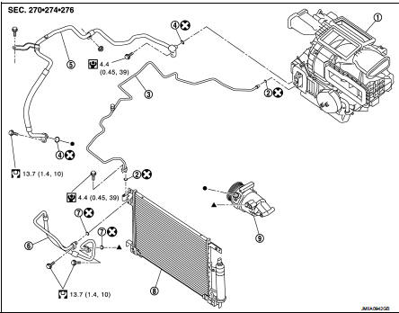
1. A/C unit assembly
2. O-ring
3. High-pressure pipe
4. O-ring
5. Low-pressure flexible hose
6. High-pressure flexible hose
7. O-ring
8. Condenser
9. Compressor
 : Do not reuse
 : N·m (kg-m, in-lb)
 : N·m (kg-m, ft-lb)
High-pressure flexible hose : Removal and Installation
CAUTION:
Perform lubricant return operation before each refrigeration system disassembly.
However, if a large
amount of refrigerant or lubricant is detected, never perform lubricant return
operation. Refer to HA-
78, "Perform Lubricant Return Operation".
REMOVAL
1. Use a refrigerant collecting equipment (for HFC-134a) to discharge the refrigerant. Refer to HA-76, "Recycle Refrigerant".
2. Remove front bumper fascia assembly. Refer to EXT-13, "Removal and Installation".
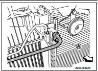
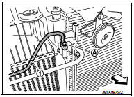
3. Remove mounting bolt (A), and then disconnect high-pressure flexible hose from condenser.
CAUTION:
Cap or wrap the joint of the A/C piping and condenser with
suitable material such as vinyl tape to avoid the entry of air.
 : Vehicle front
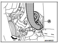
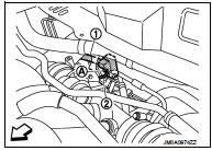
4. Remove mounting bolt (A), and then disconnect high-pressure flexible hose from compressor.
CAUTION:
Cap or wrap the joint of the A/C piping and compressor with
suitable material such as vinyl tape to avoid the entry of air.
 : Vehicle front
5. Remove high-pressure flexible hose from vehicle.
INSTALLATION
Note the following items, and then install in the reverse order of removal.
CAUTION:
• Replace O-rings with new ones. Then apply compressor oil to them when
installing.
• Check for leakages when recharging refrigerant. Refer to HA-74, "Leak Test".
Low-pressure flexible hose : Removal and Installation
CAUTION:
Perform lubricant return operation before each refrigeration system disassembly.
However, if a large
amount of refrigerant or lubricant is detected, never perform lubricant return
operation. Refer to HA-
78, "Perform Lubricant Return Operation".
REMOVAL
1. Use a refrigerant collecting equipment (for HFC-134a) to discharge the refrigerant. Refer to HA-76, "Recycle Refrigerant".
2. Remove front bumper fascia asembly. Refer to EXT-13, "Removal and Installation".
3. Remove cowl top extension. Refer to EXT-20, "Removal and Installation".
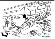
4. Remove mounting nut, and then move lower dash insulator aside.
 : Nut
: Nut
 : Vehicle front
5. Remove mounting bolt (A), and then disconnect low-pressure flexible hose (1) and high-pressure pipe (2) from expansion valve. Refer to HA-116, "EXPANSION VALVE : Removal and Installation".
CAUTION:
Cap or wrap the joint of the A/C piping and expansion valve
with suitable material such as vinyl tape to avoid the entry
of air.
: Vehicle front
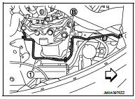
6. Remove mounting bolt (A) of low-pressure flexible hose front side (1) and mounting nut (B) of low-pressure flexible hose rear side (2).
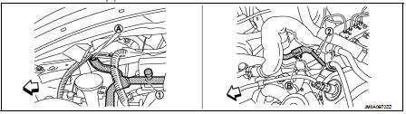
: Vehicle front
7. Remove ground wire mounting bolt (A), and then move ground wire (1) aside.
: Vehicle front
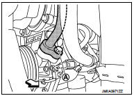
8. Remove mounting bolt (A), and then disconnect low-pressure flexible hose from compressor.
CAUTION:
Cap or wrap the joint of the A/C piping and compressor with
suitable material such as vinyl tape to avoid the entry of air.
: Vehicle front
9. Remove low-pressure flexible hose from vehicle.
INSTALLATION
Note the following items, and then install in the reverse order of removal.
CAUTION:
• Replace O-rings with new ones. Then apply compressor oil to them when
installing.
• Check for leakages when recharging refrigerant. Refer to HA-74, "Leak Test".
High-pressure pipe : Removal and Installation
CAUTION:
Perform lubricant return operation before each refrigeration system disassembly.
However, if a large
amount of refrigerant or lubricant is detected, never perform lubricant return
operation. Refer to HA-
78, "Perform Lubricant Return Operation".
REMOVAL
1. Use a refrigerant collecting equipment (for HFC-134a) to discharge the refrigerant. Refer to HA-76, "Recycle Refrigerant".
2. Remove low-pressure flexible hose. Refer to HA-91, "LOW-PRESSURE FLEXIBLE HOSE : Removal and Installation".
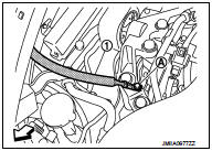
3. Remove mounting bolt (A), and then disconnect high-pressure pipe (1) from condenser.
CAUTION:
Cap or wrap the joint of the A/C piping and condenser with
suitable material such as vinyl tape to avoid the entry of air.
: Vehicle front
4. Remove high-pressure pipe (1) fixing clips (B), and then remove high-pressure pipe from vehicle.
: Vehicle front
INSTALLATION
Note the following items, and then install in the reverse order of removal.
CAUTION:
• Replace O-rings with new ones. Then apply compressor oil to them when
installing.
• Check for leakages when recharging refrigerant. Refer to HA-74, "Leak Test".
 Compressor
Exploded View
REMOVAL
1. High-pressure flexible hose
2. O-ring
3. Compressor
4. O-ring
5. Low-pressure flexible hose
A. To condenser
B. To evaporator
: N·m (kg-m, ft-lb)
DISASSEMBLY
...
 Condenser
Exploded View
1. Condenser
2. Condenser lower bracket RH
3. Condenser lower bracket LH
4. O-ring
5. Liquid tank braket
6. Liquid tank
7. Braket
8. O-ring
9. Refrigerant pressure senso ...
Other materials:
Component parts
Body control system
BODY CONTROL SYSTEM : Component Parts Location
RHD MODELS
1. BCM
A. Behind of glove box (Left side)
LHD MODELS
1. BCM
A. Behind of instrument lower panel LH
(Left side)
Power consumption control system
POWER CONSUMPTION CONTROL SYSTEM : Component Parts Location
1 ...
Insufficient cooling
Description
Symptom
• Insufficient cooling
• No cool air comes out. (Air flow volume is normal.)
Diagnosis Procedur
NOTE:
Perform self-diagnosis with CONSULT-III before performing symptom diagnosis. If
any malfunction result or
DTC is detected, perform the corresponding diagnosis.
1. ...
Back door window glass
Exploded View
1. Back door window glass
2. Spacer
3. Back door window glass holder
4. Back door window glass molding
5. Pivot seal
6. Adhesive
7. Primer
8. Back door outer
9. Back door inner
Unit: mm (in)
: Do not reuse
Removal and Installation
REMOVAL
1. Remove back door lower ...
