Nissan Juke Service and Repair Manual : Condenser
Exploded View
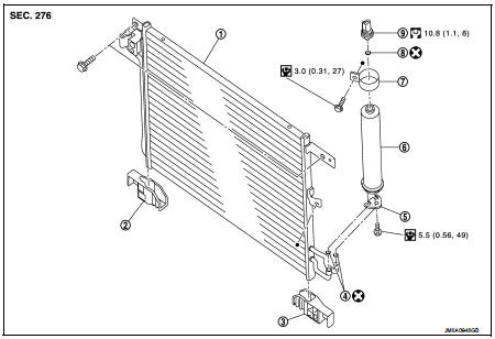
1. Condenser
2. Condenser lower bracket RH
3. Condenser lower bracket LH
4. O-ring
5. Liquid tank braket
6. Liquid tank
7. Braket
8. O-ring
9. Refrigerant pressure sensor
 : Do not reuse
 : N┬Ěm (kg-m, in-lb)
 : N┬Ěm (kg-m, ft-lb)
Condenser : Removal and Installation
CAUTION:
Perform lubricant return operation before each refrigeration system disassembly.
However, if a large
amount of refrigerant or lubricant is detected, never perform lubricant return
operation. Refer to HA-
78, "Perform Lubricant Return Operation".
REMOVAL
1. Use a refrigerant collecting equipment (for HFC-134a) to discharge the refrigerant. Refer to HA-76, "Recycle Refrigerant".
2. Remove front bumper fascia assembly. Refer to EXT-13, "Removal and Installation".
3. Remove air guide (LH). Refer to DLK-149, "MR16DDT : Exploded View".
4. Disconnect refrigerant pressure sensor harness connector.
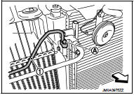
5. Remove mounting bolt (A), and then disconnect high-pressure pipe (1) from condenser.
CAUTION:
Cap or wrap the joint of the A/C piping and condenser with
suitable material such as vinyl tape to avoid the entry of air.
 : Vehicle front
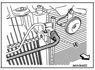
6. Remove mounting bolt (A), and then disconnect high-pressure flexible hose from condenser.
CAUTION:
Cap or wrap the joint of the A/C piping and condenser with
suitable material such as vinyl tape to avoid the entry of air.
 : Vehicle front
7. Remove mounting bolts, and then remove condenser from the vehicle.
CAUTION:
Be careful not to damage core surface of condenser.
INSTALLATION
Note the following items, and then install in the reverse order of removal.
CAUTION:
ÔÇó Replace O-rings with new ones. Then apply compressor oil to them when
installing.
ÔÇó Perform lubricant adjusting procedure before installing new condenser. Refer to HA-79, "Lubricant Adjusting Procedure for Compressor Replacement".
ÔÇó Check for leakages when recharging refrigerant. Refer to HA-74, "Leak Test".
Liquid tank : Removal and Installation
CAUTION:
Perform lubricant return operation before each refrigeration system disassembly.
However, if a large
amount of refrigerant or lubricant is detected, never perform lubricant return
operation. Refer to HA-
78, "Perform Lubricant Return Operation".
REMOVAL
1. Use a refrigerant collecting equipment (for HFC-134a) to discharge the refrigerant. Refer to HA-76, "Recycle Refrigerant".
2. Remove front bumper fascia assembly. Refer to EXT-13, "Removal and Installation".
3. Remove air guide (LH). Refer to DLK-149, "MR16DDT : Exploded View".
4. Clean liquid tank and its surrounding area, and then remove dust and rust from liquid tank.
5. Diconnect refrigerant pressure sensor harness connector.
6. Remove mounting bolts, and then remove liquid tank from condenser.
CAUTION:
Cap or wrap the joint of the A/C piping and liquid tank with suitable material
such as vinyl tape to
avoid the entry of air.
INSTALLATION
Note the following items, and install in the reverse order of removal.
CAUTION
:
ÔÇó Replace O-rings of the A/C piping with new ones. Then apply compressor oil to
them when installing.
ÔÇó Perform lubricant adjusting procedure before installing new liquid tank. Refer to HA-79, "Lubricant Adjusting Procedure for Compressor Replacement".
ÔÇó Check for leakages when recharging refrigerant. Refer to HA-74, "Leak Test".
Refrigerant pressure sensor : Removal and Installation
CAUTION:
Perform lubricant return operation before each refrigeration system disassembly.
However, if a large
amount of refrigerant or lubricant is detected, never perform lubricant return
operation. Refer to HA-
78, "Perform Lubricant Return Operation".
REMOVAL
1. Use a refrigerant collecting equipment (for HFC-134a) to discharge the refrigerant. Refer to HA-76, "Recycle Refrigerant".
2. Remove front bumper fascia. Refer to EXT-13, "Removal and Installation".
3. Clean refrigerant pressure sensor and its surrounding area, and then remove dust and rust from refrigerant pressure sensor.
4. Disconnect refrigerant pressure sensor connector.
5. Use a adjustable wrench or other tool to hold the refrigerant pressure sensor mounting block, and then remove the refrigerant pressure sensor from condenser.
CAUTION:
ÔÇó Be careful not to damage core surface of condenser.
ÔÇó Cap or wrap the joint of the condenser and liquid tank with suitable material such as vinyl tape to avoid the entry of air.
INSTALLATION
Note the following items, and then install in the reverse order of removal.
CAUTION:
ÔÇó Replace O-ring with new one. Then apply compressor oil to them when
installing.
ÔÇó Check for leakages when recharging refrigerant. Refer to HA-74, "Leak Test".
 Cooler pipe and hose
Exploded View
1. A/C unit assembly
2. O-ring
3. High-pressure pipe
4. O-ring
5. Low-pressure flexible hose
6. High-pressure flexible hose
7. O-ring
8. Condenser
9. Compressor
: Do not ...
 A/C unit assembly
Exploded View (Automatic Air Conditioning)
REMOVAL
LHD models (4WD)
1. A/C unit assembly
2. Drain hose
3. Steering member
4. Instrument stay
: Clip
: N┬Ěm (kg-m, ft-lb)
DISASSEMBLY
LHD m ...
Other materials:
System
POWER WINDOW SYSTEM
POWER WINDOW SYSTEM : System Diagram
POWER WINDOW SYSTEM : System Description
ÔÇó Power window system is activated by power window switch when ignition
switch turns ON.
ÔÇó Power window main switch opens/closes all door glass.
ÔÇó Front and rear power window switch opens ...
Wiring diagram
Engine control system
Wiring Diagram
For connector terminal arrangements, harness layouts, and alphabets in a
(option abbreviation; if not
described in wiring diagram), refer to GI-12, "Connector Information/Explanation
of Option Abbreviation".
...
Precaution for Supplemental Restraint System (SRS) "AIR BAG" and "SEAT BELT
PRE-TENSIONER"
The Supplemental Restraint System such as ÔÇťAIR BAGÔÇŁ and ÔÇťSEAT BELT PRE-TENSIONERÔÇŁ,
used along
with a front seat belt, helps to reduce the risk or severity of injury to the
driver and front passenger for certain
types of collision. Information necessary to service the system safely is
...
