Nissan Juke Service and Repair Manual : Compressor
Exploded View
REMOVAL
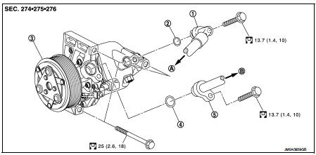
1. High-pressure flexible hose
2. O-ring
3. Compressor
4. O-ring
5. Low-pressure flexible hose
A. To condenser
B. To evaporator
 : N·m (kg-m, ft-lb)
DISASSEMBLY
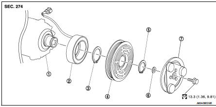
1. Compressor unit
2. Field coil
3. Snap ring
4. Pulley assembly
5. Snap ring
6. Shim
7. Clutch disc
 : N·m (kg-m, ft-lb)
Compressor : Removal and Installation
CAUTION:
Perform lubricant return operation before each refrigeration system disassembly.
However, if a large
amount of refrigerant or lubricant is detected, never perform lubricant return
operation. Refer to HA-
78, "Perform Lubricant Return Operation".
REMOVAL
1. Use a refrigerant collecting equipment (for HFC-134a) to discharge the refrigerant. Refer to HA-76, "Recycle Refrigerant".
2. Remove drive belt. Refer to EM-20, "Removal and Installation".
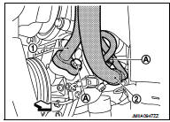
3. Remove mounting bolts (A), and then disconnect low-pressure flexible hose (1) and high-pressure flexible hose (2). (compressor side)
 : Vehicle front
CAUTION:
Cap or wrap the joint of the A/C piping and compressor with
suitable material such as vinyl tape to avoid the entry of air.
4. Disconnect magnet clutch harness connector.
 : Vehicle front
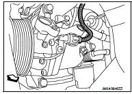
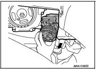
5. Remove mounting bolts. Pull out compressor in the direction indicated by an arrow as shown in the figure to remove.
CAUTION:
Be careful not to contact with and damage surrounding
parts when removing compressor from the vehicle.
INSTALLATION
Note the following items, and then install in the reverse order of removal.
CAUTION:
• Replace O-rings with new ones. Then apply compressor oil to them when
installing.
• Perform lubricant adjusting procedure before installing new compressor. Refer to HA-79, "Lubricant Adjusting Procedure for Compressor Replacement".
• Check for leakages when recharging refrigerant. Refer to HA-74, "Leak Test".
• Check tension of the drive belt after installing compressor. Refer to EM-20, "Checking".
Magnet clutch : Removal and Installation of Compressor Clutch
REMOVAL
Overhaul
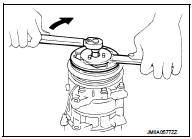
1. When removing center bolt, hold clutch disc with clutch disc
wrench (SST:KV99232340) (A).
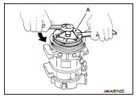
2. Remove clutch disc.
3. Remove snap ring using external snap ring pliers.
4. Position center pulley puller on the end of the drive shaft, and remove pulley assembly using any commercially available pulley puller.
To prevent pulley groove from being deformed, puller claws should be positioned into the edge of the pulley assembly.
5. Disconnect harness connector from compressor unit.
6. Remove snap ring using external snap ring pliers, and then remove field coil.
INSTALLATION
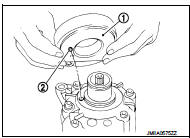
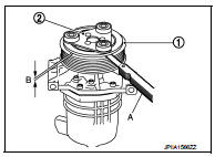
1. Install field coil (1).
Be sure to align the coil’s pin (2) with the hole in the compressor’s front head.
2. Install field coil harness clip.
3. Install pulley assembly (1) using pulley installer (SST:KV99106200) (A) and a hand press, and then install snap ring (2) using snap ring pliers.
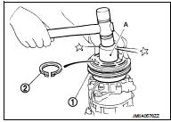
4. Install clutch disc on drive shaft, together with original shim(s). Press clutch disc down by hand.
5. Tighten center bolt to the specified torque while fixing clutch disc not to rotate using a clutch disc wrench (SST:KV99232340).
After tightening the bolt, check that the pulley rotates smoothly.
Break-in Operation
When replacing compressor clutch assembly, always perform the break-in
operation, by engaging and disengaging
the clutch approximately 30-times. Break-in operation increases the level of
transmitted torque.
Inspection
CHECK DISC TO PULLEY CLEARANCE
Check the clearance (B) between pulley assembly (1) and clutch disc (2) along the entire periphery with a feeler gauge (A).
Clearance : Refer to HA-118, "Compressor".
Replace compressor if specified clearance is not obtained.

 Cooler pipe and hose
Exploded View
1. A/C unit assembly
2. O-ring
3. High-pressure pipe
4. O-ring
5. Low-pressure flexible hose
6. High-pressure flexible hose
7. O-ring
8. Condenser
9. Compressor
: Do not ...
Other materials:
Precaution for Supplemental Restraint System (SRS) "AIR BAG" and "SEAT BELT
PRE-TENSIONER"
The Supplemental Restraint System such as “AIR BAG” and “SEAT BELT PRE-TENSIONER”,
used along
with a front seat belt, helps to reduce the risk or severity of injury to the
driver and front passenger for certain
types of collision. Information necessary to service the system safely is
...
Parts Requiring Angle Tightening
• Use the angle wrench [SST: KV10112100] for the final tightening of the
following engine parts:
- Cylinder head bolts
- Lower cylinder block bolts
- Connecting rod cap bolts
- Crankshaft pulley bolt (No the angle wrench is required as bolt flange is
provided with notches for angle
tighte ...
B26EF steering lock relay
DTC Logic
DTC DETECTION LOGIC
NOTE:
• If DTC B26EF is displayed with DTC U1000, first perform the trouble diagnosis
for DTC U1000. Refer to
BCS-83, "DTC Logic".
• If DTC B26EF is displayed with DTC U1010, first perform the trouble diagnosis
for DTC U1010. Refer to
BCS-84, &qu ...
