Nissan Juke Service and Repair Manual : 4WD branch line circuit
Diagnosis Procedure
1.CHECK CONNECTOR
1. Turn the ignition switch OFF.
2. Disconnect the battery cable from the negative terminal.
3. Check the following terminals and connectors for damage, bend and loose connection (unit side and connector side).
- 4WD control module
- Harness connecotor B7
- Harness connecotor E107
Is the inspection result normal? YES >> GO TO 2.
NO >> Repair the terminal and connector.
2.CHECK HARNESS FOR OPEN CIRCUIT
1. Disconnect the connector of 4WD control module.
2. Check the resistance between the 4WD control module harness connector terminals.
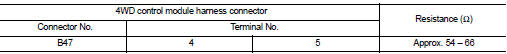
Is the measurement value within the specification? YES >> GO TO 3.
NO >> Repair the 4WD control module branch line.
3.CHECK POWER SUPPLY AND GROUND CIRCUIT
Check the power supply and the ground circuit of the 4WD control module. Refer to DLN-78, "Diagnosis Procedure".
Is the inspection result normal? YES (Present error)>>Replace the 4WD control module. Refer to DLN-91, "Removal and Installation".
YES (Past error)>>Error was detected in the 4WD control module branch line.
NO >> Repair the power supply and the ground circuit.
 ECM branch line circuit
Diagnosis Procedure
1.CHECK CONNECTOR
1. Turn the ignition switch OFF.
2. Disconnect the battery cable from the negative terminal.
3. Check the terminals and connectors of the ECM for damage, bend ...
 ABS branch line circuit
Diagnosis Procedure
1.CHECK CONNECTOR
1. Turn the ignition switch OFF.
2. Disconnect the battery cable from the negative terminal.
3. Check the terminals and connectors of the ABS actuator and ele ...
Other materials:
P0133 A/F sensor 1
DTC Logic
DTC DETECTION LOGIC
To judge the malfunction of A/F sensor 1, this diagnosis measures response
time of the A/F signal computed
by ECM from the A/F sensor 1 signal. The time is compensated by engine operating
(speed and load), fuel
feedback control constant, and the A/F sensor 1 tem ...
Harness layout
LHD
LHD : How To Read Harness Layout
CONNECTOR SYMBOL
Main symbols of connector (in Harness Layout) are indicated in the below.
LHD : Engine Room Harness
ENGINE COMPARTMENT
PASSENGER COMPARTMENT
LHD : Engine Control Harness
HR ENGINE
MR ENGINE
K9K ENGINE
LHD : Main Harness
...
P1808 Wheel speed sensor
DTC Logic
DTC DETECTION LOGIC
DTC CONFIRMATION PROCEDURE
1.PRECONDITIONING
If “DTC CONFIRMATION PROCEDURE” has been previously conducted, always turn
ignition switch OFF and
wait at least 10 seconds before conducting the next test.
>> GO TO 2.
2.DTC REPRODUCTION PROCEDURE
W ...
