Nissan Juke Service and Repair Manual : U1010 control unit (CAN)
Description
CAN (Controller Area Network) is a serial communication line for real time application. It is an on-vehicle multiplex communication line with high data communication speed and excellent malfunction detection ability.
Many electronic control units are equipped onto a vehicle, and each control unit shares information and links with other control units during operation (not independent). In CAN communication, control units are connected with 2 communication lines (CAN-H and CAN-L) allowing a high rate of information transmission with less wiring. Each control unit transmits/receives data but selectively reads required data only.
DTC Logic
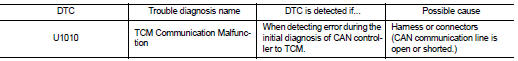
DTC DETECTION LOGIC
DTC CONFIRMATION PROCEDURE
NOTE
:
If ÔÇťDTC CONFIRMATION PROCEDUREÔÇŁ has been previously performed, always turn
ignition switch
OFF and wait at least 10 seconds before performing the next test.
After the repair, perform the following procedure to confirm the malfunction is eliminated.
1.CHECK DTC DETECTION
 With CONSULT-III
1. Turn ignition switch ON.
2. Start engine and wait for at least 6 seconds.
3. Select ÔÇťSelf Diagnostic ResultsÔÇŁ in ÔÇťTRANSMISSIONÔÇŁ.
 With GST
Follow the procedure ÔÇťWith CONSULT-IIIÔÇŁ.
Is ÔÇťU1010ÔÇŁ detected? YES >> Go to TM-196, "Diagnosis Procedure".
NO >> Check intermittent incident. Refer to GI-42, "Intermittent Incident".
Diagnosis Procedure
1.CHECK INTERMITTENT INCIDENT
Refer to GI-42, "Intermittent Incident".
Is the inspection result normal? YES >> Replace the TCM. Refer to TM-280, "Removal and Installation".
NO >> Repair or replace damaged parts.
 U1000 can comm circuit
Description
CAN (Controller Area Network) is a serial communication line for real time
application. It is an on-vehicle multiplex
communication line with high data communication speed and excellen ...
 P0703 brake switch B
Description
BCM detects ON/OFF state of the stop lamp switch and transmits the data to
the CVT control unit via CAN
communication by converting the data to a signal.
DTC Logic
DTC DETECTION LOGI ...
Other materials:
Component parts
Component Parts Location
1. Back door lock assembly
2. Front door lock assembly (driver
side)
3. Front door switch (driver side)
4. Power window main switch
(door lock/unlock switch)
5. Key switch
6. Combination meter
7. Door lock status indicator
8. Remote keyless entry receiver
9. ...
Steering gear and linkage
Exploded View
REMOVAL
LHD Models
1. Steering gear assembly
2. Heat insulator
3. Front suspension member
: Vehicle front
: Always replace after every
disassembly.
: N┬Ěm (kg-m, ft-lb)
: N┬Ěm (kg-m, in-lb)
RHD Models
1. Steering gear assembly
2. Heat insulator
3. Front suspensio ...
Sensor rotor
Front sensor rotor : Removal and Installation
REMOVAL
Replace wheel hub as an assembly when replacing because sensor rotor cannot
be disassembled. Refer to
FAX-43, "Removal and Installation".
INSTALLATION
Replace wheel hub as an assembly when replacing because sensor rotor cannot ...
