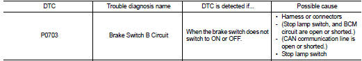
Nissan Juke Service and Repair Manual : P0703 brake switch B
Description
BCM detects ON/OFF state of the stop lamp switch and transmits the data to the CVT control unit via CAN communication by converting the data to a signal.
DTC Logic
DTC DETECTION LOGIC
DTC CONFIRMATION PROCEDURE
CAUTION:
Always drive vehicle at a safe speed.
NOTE:
If “DTC CONFIRMATION PROCEDURE” has been previously performed, always turn ignition switch OFF and wait at least 10 seconds before performing the next test.
After the repair, perform the following procedure to confirm the malfunction is eliminated.
1.CHECK DTC DETECTION
 With CONSULT-III
1. Turn ignition switch ON.
2. Start engine.
3. Start vehicle for at least 3 consecutive seconds.
4. Select “Self Diagnostic Results” in “TRANSMISSION”.
Is “P0703” detected? YES >> Go to TM-197, "Diagnosis Procedure".
NO >> Check intermittent incident. Refer to GI-42, "Intermittent Incident".
Diagnosis Procedure
1.CHECK STOP LAMP SWITCH CIRCUIT
1. Check and adjust the installation position of stop lamp switch. Refer to BR-9, "Inspection and Adjustment" (LHD), BR-77, "Inspection and Adjustment" (RHD).
2. Turn ignition switch OFF.
3. Disconnect BCM connector.
4. Turn ignition switch ON.
5. Check voltage between BCM vehicle side harness connector terminal and ground.
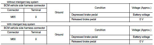
Is the inspection result normal? YES >> GO TO 5.
NO >> GO TO 2.
2.CHECK HARNESS BETWEEN STOP LAMP SWITCH AND BCM (PART 1)
1. Turn ignition switch OFF.
2. Disconnect stop lamp switch connector.
3. Check continuity between stop lamp switch vehicle side harness connector terminal and BCM vehicle side harness connector terminal.
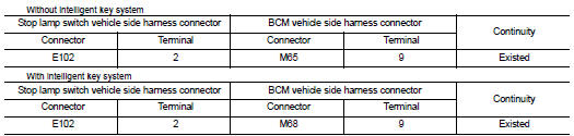
Is the inspection result normal? YES >> GO TO 3.
NO >> Repair or replace damaged parts.
3.CHECK HARNESS BETWEEN STOP LAMP SWITCH AND BCM (PART 2)
Check continuity between BCM vehicle side harness connector terminal and ground.
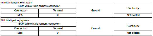
Is the inspection result normal? YES >> GO TO 4.
NO >> Repair or replace damaged parts.
4.CHECK STOP LAMP SWITCH
Check stop lamp switch. Refer to TM-199, "Component Inspection".
Is the inspection result normal? YES >> Check the following.
• Harness for short or open between battery and stop lamp switch • 10A fuse (No. 38, located in fuse block)
NO >> Repair or replace stop lamp switch.
5.CHECK BCM
With CONSULT-III
1. Turn ignition switch OFF.
2. Connect BCM connector.
3. Turn ignition switch ON.
4. Select “BRAKE SW” in “Data Monitor” in “BCM” and verify the proper operation of ON/OFF. Refer to BCS- 41, "Reference Value" (With intelligent key system), BCS-125, "Reference Value" (Without intelligent key system).
Is the inspection result normal? YES >> GO TO 6.
NO >> Replace BCM. Refer to BCS-93, "Removal and Installation" (With intelligent key system), BCS- 125, "Reference Value" (Without intelligent key system).
6.DETECT MALFUNCTIONING ITEMS
Check TCM connector pin terminals for damage or loose connection with harness connector.
Is the inspection result normal? YES >> Replace TCM. Refer to TM-280, "Removal and Installation".
NO >> Repair or replace damaged parts.
Component Inspec
1.CHECK STOP LAMP SWITCH
Check continuity between stop lamp switch connector terminals
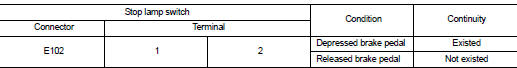
Check stop lamp switch after adjusting brake pedal — refer to BR-9, "Inspection and Adjustment" (LHD), BR-77, "Inspection and Adjustment" (RHD).
Is the inspection result normal? YES >> Check the following. If NG, repair or replace damaged parts.
• Harness for short or open between battery and stop lamp switch.
• Harness for short or open between stop lamp switch and BCM.
• 10A fuse (No. 38, located in fuse block).
NO >> Repair or replace the stop lamp switch.
 U1010 control unit (CAN)
Description
CAN (Controller Area Network) is a serial communication line for real time
application. It is an on-vehicle multiplex
communication line with high data communication speed and excellen ...
 P0705 transmission range switch A
DTC Logic
DTC DETECTION LOGIC
DTC CONFIRMATION PROCEDURE
CAUTION:
Always drive vehicle at a safe speed.
NOTE:
If “DTC CONFIRMATION PROCEDURE” has been previously performed, always turn
i ...
Other materials:
Precaution Necessary for Steering Wheel Rotation after Battery Disconnect
NOTE:
• Before removing and installing any control units, first turn the ignition
switch to the LOCK position, then disconnect
both battery cables.
• After finishing work, confirm that all control unit connectors are connected
properly, then re-connect both
battery cables.
• Always us ...
B1087 seat belt Pre-tensioner LH
DTC Logic
DTC DETECTION LOGIC
DTC CONFIRMATION PROCEDURE
1.CHECK SELF-DIAG RESULT
With CONSULT-III
1. Turn ignition switch ON.
2. Perform “Self Diagnostic Result” mode of “AIR BAG” using CONSULT-III.
Without CONSULT-III
1. Turn ignition switch ON.
2. Check the air bag warning la ...
Electric controlled coupling
Exploded View
1. Filler plug
2. Gasket
3. Drain plug
4. Breather tube
5. Clip
6. Breather hose
7. Breather
8. sub-harness clip
9. sub-harness
10. Rear cover
11. Center stem
12. Side bearing (right)
13. Side bearing adjusting shim (right)
14. Side oil seal (right)
15. Conne ...
