Nissan Juke Service and Repair Manual : Liquid Gasket
REMOVAL OF LIQUID GASKET SEALING
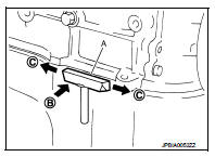
• After removing mounting nuts and bolts, separate the mating surface using the seal cutter [SST: KV10111100] (A) and remove old liquid gasket sealing.
CAUTION:
Be careful not to damage the mating surface
s.
• Tap the seal cutter [SST: KV10111100] to insert it (B), and then slide it (C) by tapping on the side as shown in the figure.
• In areas where the seal cutter [SST: KV10111100] is difficult to use, lightly tap the parts using a plastic hammer to remove it.
CAUTION:
If for some unavoidable reason tool such as a screwdriver is
used, be careful not to damage the mating surfaces.
LIQUID GASKET APPLICATION PROCEDURE
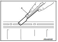
1. Using a scraper (A), remove old liquid gasket adhering to the liquid gasket application surface and the mating surface.
• Remove liquid gasket completely from the groove of the liquid gasket application surface, mounting bolts, and bolt holes.
2. Wipe the liquid gasket application surface and the mating surface with white gasoline (lighting and heating use) to remove adhering moisture, grease and foreign materials.
3. Attach liquid gasket tube to the tube presser (commercial service tool).
Use Genuine Liquid gasket or equivalent.
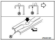
4. Apply liquid gasket without gaps to the specified location according to the specified dimensions.
• If there is a groove for liquid gasket application, apply liquid gasket to the groove.
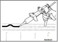
• As for bolt holes (B), normally apply liquid gasket inside the holes. Occasionally, it should be applied outside the holes.
Check to read the text of this manual.
A : Groove
 : Inside
• Within five minutes of liquid gasket application, install the mating component.
• If liquid gasket protrudes, wipe it off immediately.
• Do not retighten mounting bolts or nuts after the installation.
• After 30 minutes or more have passed from the installation, fill engine oil and engine coolant.
CAUTION
:
If there are specific instructions in this manual, observe them.
 Precaution
...

Other materials:
B1116 satellite sensor RH
DTC Logic
DTC DETECTION LOGIC
DTC CONFIRMATION PROCEDURE
1.CHECK SELF-DIAG RESULT
With CONSULT-III
1. Turn ignition switch ON.
2. Perform “Self Diagnostic Result” mode of “AIR BAG” using CONSULT-III.
Without CONSULT-III
1. Turn ignition switch ON.
2. Check the air bag warning la ...
P1739 1GR incorrect ratio
DTC Logic
DTC DETECTION LOGIC
DTC CONFIRMATION PROCEDURE
CAUTION:
• Be sure to perform “TM-442, "Diagnosis Procedure"” and then perform “DTC
CONFIRMATION PROCEDURE”.
• Never perform "DTC CONFIRMATION PROCEDURE" before the repairs. Doing so may
result in a s ...
Idle air volume learning
Description
Idle Air Volume Learning is a function of ECM to learn the idle air volume
that keeps each engine idle speed
within the specific range. It must be performed under any of the following
conditions:
• Each time electric throttle control actuator or ECM is replaced.
• Idle speed ...
