Nissan Juke Service and Repair Manual : Speed limiter
SPEED LIMITER : Switch Name and Function
SWITCHES AND INDICATORS
NOTE
:
Shared with ASCD switch.
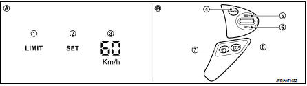
1. Speed limiter indicator
2. SET indicator
3. Set speed indicator
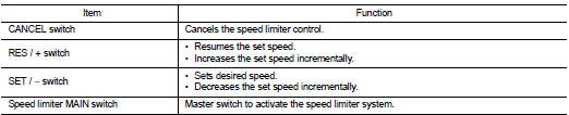
4. CANCEL switch
5. RES / + switch
6. SET / − switch
7. Speed limiter MAIN Switch
8. ASCD MAIN switch
A. On the combination meter
(Information display)
B. On the steering wheel
SET SPEED RANGE
Speed limiter system can be set the following vehicle speed.

SWITCH OPERATION
SET OPERATION
• Press speed limiter MAIN switch. (LIMIT indicated on the information
display)
• By pressing the SET/− switch, the vehicle speed can be set within the range
between 30 km/h and 210 km/h
(in the metric system mode) or 20 MPH and 130 MPH (in the yard/pound system
mode). (SET and set speed
is indicated on the information display)
• When pressing the RES/+ switch, the set speed can be increased.
• When pressing the SET/− switch, the set speed can be decreased.
CANCEL CONDITION
• When any of following conditions exist, speed limiter control is canceled.
- Speed limiter MAIN switch is pressed. (Set speed is cleared.) - ASCD MAIN switch is pressed. (Set speed is cleared.) - CANCEL switch is pressed.
• When accelerator pedal is fully depressed (Kickdown), speed limiter control is temporarily released. And driver can be driven above set speed (Set speed indicator is blinked).
• When the ECM detects any of the following conditions, the ECM cancels the speed limiter operation and informs the driver by blinking speed limiter indicator and SET indicator.
- Malfunction for some self-diagnosis regarding ASCD system.
RESUME OPERATION
After the speed limiter is released by other method than the MAIN switch, the RES/+ switch allows to set the vehicle speed again to the one that is previously set before releasing the speed limiter.
 Operation
AUTOMATIC SPEED CONTROL DEVICE (ASCD)
AUTOMATIC SPEED CONTROL DEVICE (ASCD) : Switch Name and Function
SWITCHES AND INDICATORS
1. CRUISE indicator
2. SET indicator
3. CANCEL switch
4. RES / ...
 On board diagnostic (OBD) system
Diagnosis Description
This system is an on board diagnostic system that records exhaust
emission-related diagnostic information
and detects a sensors/actuator-related malfunction. A malfunction is ...
Other materials:
P0420 three way catalyst function
DTC Logic
DTC DETECTION LOGIC
The ECM monitors the switching frequency ratio of air fuel ratio (A/F)
sensor 1 and heated oxygen sensor 2.
A three way catalyst (manifold) with high oxygen storage capacity
will indicate a low switching frequency of heated oxygen sensor 2.
As oxygen storage c ...
Booster seats
For detailed guidance on safely installing a booster seat within your Nissan Leaf, please carefully follow the instructions and safety standards outlined in this section.
Precautions on booster seats
WARNING
Improper use of a booster seat or the vehicle's seat belt significantly incre ...
Service
• Never use electrical test equipment to check SRS circuits unless instructed
to in this Service Manual.
• Before servicing the SRS, turn ignition switch OFF, disconnect battery
negative terminal and wait 3 minutes
or more. For approximately 3 minutes after the cables are removed, it is st ...
