Nissan Juke Service and Repair Manual : SPEED LIMITER MAIN SWITCH
Component Function Check
1.CHECK SPEED LIMITER MAIN SWITCH FUNCTION
 With CONSULT-III
1. Turn ignition switch ON.
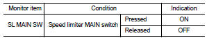
2. Select ÔÇťSL MAIN SWÔÇŁ in ÔÇťDATA MONITORÔÇŁ mode of ÔÇťENGINEÔÇŁ using CONSULT-III.
3. Check ÔÇťSL MAIN SWÔÇŁ indication as per the following condition.
 Without CONSULT-III
1. Turn ignition switch ON.
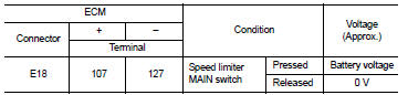
2. Check the voltage between ECM harness connector and ground as per the following conditions.
Is the inspection result normal? YES >> INSPECTION END
NO >> Proceed to EC-432, "Diagnosis Procedure".
Diagnosis Procedure
1.CHECK SPEED LIMITER MAIN SWITCH POWER SUPPLY
1. Turn ignition switch OFF.
2. Disconnect combination switch (spiral cable) harness connector.
3. Turn ignition switch ON.
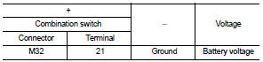
4. Check the voltage between combination switch harness connector and ground.
Is the inspection result normal? YES >> GO TO 2.
NO >> Perform the trouble diagnosis for power supply circuit.
2.CHECK SPEED LIMITER MAIN SWITCH INPUT SIGNAL CIRCUIT
1. Turn ignition switch OFF.
2. Disconnect ECM harness connector.
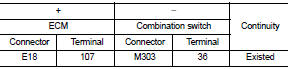
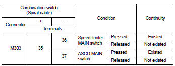
3. Check the continuity between ECM harness connector and combination switch harness connector.
4. Also check harness for short to ground and to power.
Is the inspection result normal? YES >> GO TO 3.
NO >> Repair or replace error-detected parts.
3.CHECK ASCD STEERING SWITCH
Check the ASCD steering switch. Refer to EC-433, "Component Inspection".
Is the inspection result normal? YES >> Check intermittent incident. Refer to GI-42, "Intermittent Incident".
NO >> Replace ASCD steering switch. Refer to ST-9, "Exploded View".
Component Inspection
1.CHECK ASCD STEERING SWITCH-I
1. Disconnect combination switch (spiral cable) harness connector.
2. Check the continuity between combination switch harness connector terminals as per the following conditions.
Is the inspection result normal? YES >> INSPECTION END
NO >> Replace ASCD steering switch. Refer to ST-9, "Exploded View".
2.CHECK ASCD STEERING SWITCH
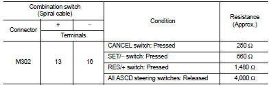
1. Disconnect combination switch (spiral cable) harness connector.
2. Check the resistance between combination switch harness connector terminals as per the following conditions.
Is the inspection result normal? YES >> INSPECTION END
NO >> Replace ASCD steering switch. Refer to ST-9, "Exploded View".
 ASCD main switch
Component Function Check
1.CHECK ASCD MAIN SWITCH FUNCTION
With CONSULT-III
1. Turn ignition switch ON.
2. Select ÔÇťMAIN SWÔÇŁ in ÔÇťDATA MONITORÔÇŁ mode of ÔÇťENGINEÔÇŁ using CONSULT-III.
3. Ch ...
 Information display (ASCD)
Component Function Check
1.CHECK INFORMATION DISPLAY
1. Start engine.
2. Press ASCD MAIN switch on ASCD steering switch.
3. Drive the vehicle at more than 40 km/h (25 MPH).
CAUTION:
Always dri ...
Other materials:
Inspection
OIL LEAKAGE
Check transfer surrounding area (oil seal, drain plug, filler plug, and
transfer case etc.) for oil leakage.
OIL LEVEL
1. Remove filler plug (1) and gasket. Then check that oil is filled up
from mounting hole for the filler plug.
Vehicle front
CAUTION:
Never start engine while ...
How to switch the display
With the primary power switch sitting in the active ON position, you can easily activate the system by pressing the physical hardware CAMERA button on the console bezel or by moving the electronic shift selector lever into the R (Reverse) position to automatically operate the Intelligent Around View ...
P1723 speed sensor
Description
The secondary speed sensor detects the revolution of parking gear and
generates a pulse signal. The pulse
signal is sent to the TCM, which converts it into vehicle speed.
The prymary speed sensor detects the primary pulley revolution speed and sends a
signal to the TCM.
DTC Log ...
