Nissan Juke Service and Repair Manual : Fan control amplifier
Exploded View
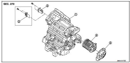
1. A/C unit assembly
2. Fan control amp.*1
3. Blower fan resistor*2
4. Blower motor
5. Blower motor cover
• *1: Automatic air conditioner • *2: Manual air conditioner
Removal and Installation
REMOVAL
1. Remove instrument panel assembly. Refer to IP-13, "Removal and
Installation". (LHD models)
2. Remove glove box assembly. Refer to IP-13, "Removal and Installation". (RHD
models)
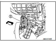
3. Disconnect fan control amp. connector.
4. Remove fixing screws (A), and then remove fan control amp.
(1).
INSTALLATION Install in the reverse order of removal.
 Refrigerant pressure sensor
Exploded View
Refer to HA-39, "Exploded View". (HR16DE)
Refer to HA-94, "Exploded View". (MR16DDT)
Removal and Installation
REMOVAL
Refer to HA-42, "REFRIGERANT PRESSURE ...
 Door motor
Exploded View
LEFT SIDE
1. A/C unit assembly
2. Intake door lever
3. Intake door link
4. Intake door motor
5. Air mix door motor
6. Air mix door link
7. Max. cool door
8. Upper air mix ...
Other materials:
B20A0 cranking request circuit
DTC Logic
DTC DETECTION LOGIC
NOTE:
If DTC B20A0 is displayed with DTC U1000, first perform the trouble diagnosis
for DTC U1000. Refer to PCS-
59, "DTC Logic".
DTC CONFIRMATION PROCEDURE
1.PERFORM DTC CONFIRMATION PROCEDURE
1. Perform DTC CONFIRMATION PROCEDURE for DTC P1650. Re ...
Vehicle speed sensing auto lock operation does not operate
Diagnosis Procedure
1.CHECK “AUTOMATIC LOCK/UNLOCK SELECT” SETTING IN “WORK SUPPORT”
1. Select “DOOR LOCK” of “BCM” using CONSULT-III.
2. Select “AUTOMATIC LOCK/UNLOCK SELECT” in “WORK SUPPORT” mode.
3. Check “AUTOMATIC LOCK/UNLOCK SELECT” in “WORK SUPPORT”.
Re ...
Door does not lock/unlock with door lock and unlock
switch
All door
ALL DOOR : Description
All doors do not lock/unlock using door lock and unlock switch.
ALL DOOR : Diagnosis Procedure
1.CHECK DOOR LOCK AND UNLOCK SWITCH
Check door lock and unlock switch.
Refer to DLK-520, "Component Function Check".
Is the inspection result normal?
Y ...
