Nissan Juke Service and Repair Manual : Door motor
Exploded View
LEFT SIDE
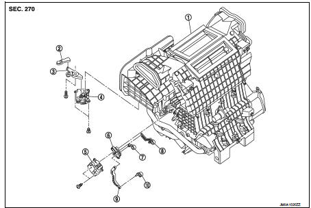
1. A/C unit assembly
2. Intake door lever
3. Intake door link
4. Intake door motor
5. Air mix door motor
6. Air mix door link
7. Max. cool door
8. Upper air mix door lever
9. Air mix door rod
10. Lower air mix door lever
RIGHT SIDE
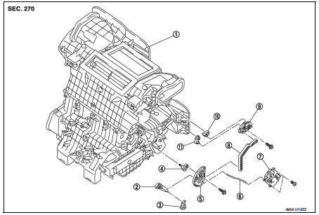
1. A/C unit assembly
2. Foot door link
3. Foot door lever
4. Side ventilator door lever
5. Mode door main link
6. Mode door link rod
7. Mode door motor
8. Mode door main link adapter rod
9. Mode door main link adapter
10. Defroster door lever
11. Center ventilator door lever
Intake door motor : Removal and Installation
REMOVAL
1. Remove instrument lower panel LH. Refer to IP-13, "Removal and
Installation". (LHD models)
2. Remove glove box assembly. Refer to IP-13, "Removal and Installation". (RHD
models)
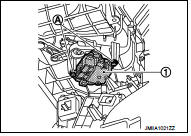
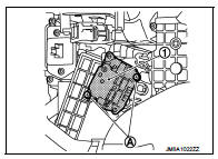
3. Disconnect intake door motor connector.
4. Remove fixing screws (A), and then remove intake door motor (1) from A/C unit assembly.
INSTALLATION
Install in the reverse order of removal.
Mode door motor : Removal and Installation
REMOVAL
1. Remove glove box assembly Refer to IP-13, "Removal and Installation". (LHD
models)
2. Remove instrument lower panel RH. Refer to IP-13, "Removal and Installation".
(RHD models)
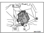
3. Disconnect mode door motor connector.
4. Disconnect mode door link rod from mode door motor (1).
5. Remove fixing screws (A), and then remove mode door motor from A/C unit assembly.
INSTALLATION
Install in the reverse order of removal.
Air mix door motor : Removal and Installation
REMOVAL
1. Remove instrument lower panel LH. Refer to IP-13, "Removal and
Installation". (LHD models)
2. Remove glove box assembly. Refer to IP-13, "Removal and Installation". (RHD
models)
3. Disconnect air mix door motor harness connector.
4. Remove fixing screws (A), and then remove air mix door motor (1) from A/C unit assembly.
INSTALLATION
Install in the reverse order of removal.
 Fan control amplifier
Exploded View
1. A/C unit assembly
2. Fan control amp.*1
3. Blower fan resistor*2
4. Blower motor
5. Blower motor cover
ŌĆó *1: Automatic air conditioner
ŌĆó *2: Manual air conditioner
Re ...

Other materials:
For side and rollover collision : When SRS is not activated in a collision
CAUTION:
Due to varying models and option levels, not all parts listed in the chart below
apply to all vehicles.
WORK PROCEDURE
1. Before performing any of the following steps, ensure that all vehicle body
and structural repairs have been
completed.
2. Check the SRS components and the rel ...
Cooling system
The cooling system in your Nissan Leaf is factory-filled with a high-performance, pre-diluted mixture consisting of 50% Genuine NISSAN Long Life Antifreeze/Coolant (blue) and 50% demineralized water. This specialized formulation is designed to provide comprehensive, year-round protection against bot ...
B1074, B1075, B1076, B1077, B1078, B1079 diagnosis sensor unit
DTC Logic
DTC DETECTION LOGIC
DTC CONFIRMATION PROCEDURE
1.CHECK SELF-DIAG RESULT
With CONSULT-III
1. Turn ignition switch ON.
2. Perform ŌĆ£Self Diagnostic ResultŌĆØ mode of ŌĆ£AIR BAGŌĆØ using CONSULT-III.
Without CONSULT-III
1. Turn ignition switch ON.
2. Check the air bag warning la ...
