Nissan Juke Service and Repair Manual : Hoses
HOSE REMOVAL AND INSTALLATION
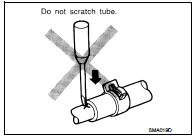
• To prevent damage to rubber hose, do not pry off rubber hose with tapered tool or screwdriver.
• To reinstall the rubber hose securely, check that hose insertion length and orientation is correct. (If tube is equipped with hose stopper, insert rubber hose into tube until it butts up against hose stopper.)
HOSE CLAMPING
• If old rubber hose is re-used, install hose clamp in its original position (at the indentation where the old clamp was). If there is a trace of tube bulging left on the old rubber hose, align rubber hose at that position.
• Discard old clamps; replace with new ones.
• After installing plate clamps, apply force to them in the direction of the arrow, tightening rubber hose equally all around.
 Turbocharger (If Equipped)
The turbocharger turbine revolves at extremely high speeds and
becomes very hot. Therefore, it is essential to maintain a clean supply
of oil flowing through the turbocharger and to follow all requi ...
 Engine Oils
Prolonged and repeated contact with used engine oil may cause skin cancer.
Try to avoid direct skin contact
with used oil.
If skin contact is made, wash thoroughly with soap or hand cleaner as s ...
Other materials:
Precautions when starting and driving
WARNING
Do not leave young children or adults who would normally require the physical support of others unattended or alone in your vehicle. Pets should not be left alone inside the cabin either. They could accidentally injure themselves or others through the inadvertent operation of ...
Charge connector lock system
To provide enhanced security and peace of mind during public charging sessions, the Nissan Leaf is equipped with an integrated charge connector lock system. This feature allows you to securely lock your normal or trickle charge connector to the vehicle's charge port, preventing ...
Squeak and rattle trouble diagnoses
Work Flow
CUSTOMER INTERVIEW
Interview the customer if possible, to determine the conditions that exist
when the noise occurs. Use the Diagnostic
Worksheet during the interview to document the facts and conditions when the
noise occurs and any of
customer's comments; refer to DLK-302, &quo ...
