Nissan Juke Service and Repair Manual : Fuel injector and fuel tube
Exploded View
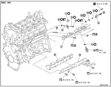
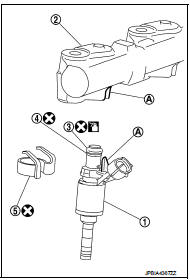
1. Holder
2. Seal ring (white)
3. Backup ring
4. O-ring (blue)
5. Fuel injector
6. Stud bolt
7. Fuel tube assembly
8. Fuel tube insulator
9. Fuel tube protector
10. Fuel pressure sensor
11. O-ring
12. Fuel tube adaptor
13. Backup ring (white)
14. Backup ring (brown)
15. O-ring (black)
A. To fuel tube
B. Tighting must be done following the installation
procedure. Refer to EM-47
 : N·m (kg-m, ft-lb)
 : N·m (kg-m, in-lb)
 : Always replace after every
disassembly.
 : Should be lubricated with oil.
CAUTION:
Never remove or disassemble parts unless instructed as shown in the figure.
Removal and Installation
WARNING:
• Be sure to read EM-7, "Precaution for Handling High Pressure Fuel System" when
working on the
high pressure fuel system.
• Put a “CAUTION: FLAMMABLE” sign in the workshop.
• Be sure to work in a well ventilated area and furnish workshop with a CO2 fire extinguisher.
• Never smoke while servicing fuel system. Keep open flames and sparks away from the work area.
• To avoid the danger of being scalded, never drain engine coolant when engine is hot.
REMOVAL
1. Release the fuel pressure. Refer to EC-140, "Work Procedure".
2. Remove front bumper. Refer to EXT-12, "Exploded View" 3. Remove charge are cooler. Refer to EM-31, "Exploded View".
4. Remove oil level gauge. Refer to EM-40, "Exploded View".
5. Remove intake manifold. Refer to EM-28, "Exploded View".
6. Remove alternator. Refer to CHG-30, "MR16DDT : Exploded View" 7. Remove oil level gauge guide. Refer to EM-40, "Exploded View".
8. Remove fuel tube protector, and them remove fuel tube insulator.
9. Remove high pressure pump insulator. Refer to EM-43, "Exploded View".
10. Remove fuel tube. Refer to EM-43, "Exploded View".
11. Disconnect fuel pressure sensor harness connector.
12. Disconnect fuel injector harness connector.
13. Remove fuel tube.
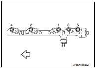
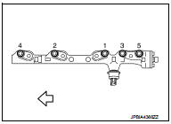
• Loosen mounting bolts in reverse order as shown in the figure.
 : Engine front
CAUTION:
• When removing, be careful to avoid any interference with fuel
injector.
• Use a shop cloth to absorb any fuel leakage from fuel tube.
14. Remove fuel pressure sensor and fuel tube adaptor, if necessary.
15. Remove fuel injector from cylinder head as per the following.
CAUTION:
• Be careful with remaining fuel that may go out from fuel tube.
• Be careful no to damage injector nozzles during removal.
• Never bump or drop fuel injector.
• Never disassemble fuel injector.
a. Remove injector holder.
b. Install an remover [SST: KV10119600] (A) to the injector connector side so that cutout (B) of injector remover faces the injector connector side.
![• Hook pawl portion (B) of injector remover [SST: KV10119600]](images/books/335/2/index.19.jpg)
• Hook pawl portion (B) of injector remover [SST: KV10119600] (A) to groove portion (C) of injector
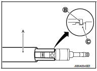
c. Press down body portion (A) of injector remover [SST: KV10119600] until it contacts cylinder head.
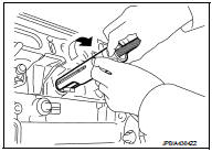
![d. Tighten injector remover [SST: KV10119600] clockwise and](images/books/335/2/index.26.jpg)
d. Tighten injector remover [SST: KV10119600] clockwise and remove injector from cylinder head.
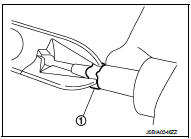
e. Cut teflon seal (1) while pinching it. Be careful not to damage injector.
f. Remove insulator from mounting hole of fuel injector of cylinder head.
INSTALLATION
1. Install seal ring to fuel injector as per the following:
CAUTION:
• Handle seal ring with bare hands. Never wear gloves.
• Never apply engine oil to seal ring.
• Never clean seal ring with solvent.
a. Install an injector seal drift set [SST: KV101197S0 (—)] (A) to fuel injector (1).
![b. Set seal ring (1) to injector seal drift set [SST: KV101197S0 (—)]](images/books/335/2/index.38.jpg)
b. Set seal ring (1) to injector seal drift set [SST: KV101197S0 (—)] (A).
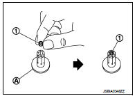
c. Straightly insert seal ring (1), which is set in step 2, to fuel injector as shown in the figure and install.
CAUTION:
Be careful that seal ring does not exceed the groove portion
of fuel injector.
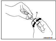
![d. Insert injector seal drift set [SST: KV101197S0 (—)] (A) to injector](images/books/335/2/index.45.jpg)
d. Insert injector seal drift set [SST: KV101197S0 (—)] (A) to injector and rotate clockwise and counterclockwise by 90° while pressing seal ring to fit it.
NOTE
:
Compress seal ring, because this operation is for rectifying
stretch of seal ring caused by installation and for preventing
sticking when inserting injector into cylinder head.
2. Install O-ring and backup ring to fuel injector. When handing new O-ring
and backup ring, paying attention
to the following caution items:
CAUTION:
• Handle O-ring with bare hands. Never wear gloves.
• Lubricate O-ring with new engine oil.
• Never clean O-ring with solvent.
• Check that O-ring and its mating part are free of foreign material.
• When installing O-ring, be careful not to scratch it with tool or fingernails. Also be careful not to twist or stretch O-ring. If O-ring was stretched while it was being attached, never insert it quickly into fuel tube.
• Insert new O-ring straight into fuel rail. Never decenter or twist it.
• Always install the back up ring (1) in the right direction as instructed.
3. Install fuel injector (1) to fuel rail (2) as per the following:
3 : O-ring (blue)
4 : Backup ring
a. Install fuel injector holder (5) to fuel injector.
CAUTION:
• Never reuse injector holder. Replace it with a new one.
• Be careful to keep fuel injector holder from interfering with O-ring. If interference occurs, replace O-ring.
b. Insert fuel injector into fuel rail with fuel injector holder attached.
• Insert it while matching it to the axial center.
• Insert so that protrusion (A) of fuel injector is aligned to cutout (B).
c. Check that installation is complete by checking that fuel injector does not rotate or come off.
• Check that protrusions of fuel injectors and fuel rail are aligned with cutouts of clips after installation.
4. Insert insulator into mounting hole of fuel injector of cylinder head.
5. Install fuel pressure sensor, if removed.
6. Install fuel tube adaptor, if removed.
• Install O-ring and backup ring to fuel tube adaptor. When handing new O-ring
and backup ring, paying
attention to the following caution items:
CAUTION:
• Handle O-ring with bare hands. Never wear gloves.
• Lubricate O-ring with new engine oil.
• Never clean O-ring with solvent.
• Check that O-ring and its mating part are free of foreign material.
• When installing O-ring, be careful not to scratch it with tool or fingernails. Also be careful not to twist or stretch O-ring. If O-ring was stretched while it was being attached, never insert it quickly into fuel tube.
• Insert new O-ring straight into fuel rail. Never decenter or twist it.
• Always install the back up ring in the right direction as instructed.
- Since the cross sections of fuel tube adapter and back up ring are tapered, be careful with the mounting direction.
7. Install fuel rail and fuel injector assembly to cylinder head.
• Tighten mounting bolts and nuts in two steps in numerical order as shown in the figure.
 : Engine front
1st step  : 10.0 N·m (1.0 kg-m, 89
in-lb)
2nd step  : 20.5 N·m (2.1 kg-m, 15
ft-lb)
8. Connect injector harness connector.
9. Install in the reverse order of removal after this step.
Inspection
Check on Fuel Leakage 1. Turn ignition switch “ON” (with the engine stopped). With fuel pressure applied to fuel piping, check there are no fuel leakage at connection points.
NOTE
:
Use mirrors for checking at points out of clear sight.
2. Start the engine. With engine speed increased, check again that there are no fuel leakage at connection points.
CAUTION:
Never touch the engine immediately after stopped, as the engine becomes
extremely hot.
 High pressure fuel pump and fuel hose
Exploded View
CAUTION:
Never remove or disassemble parts unless instructed as shown in the figure.
1. High pressure fuel pump insulator
2. High pressure fuel pump
3. O-ring
4. Valve lifter ...
 Ignition coil, spark plug and rocker cover
Exploded View
1. Rocker cover protector
2. O-ring
3. PCV control valve
4. PCV hose
5. Clamp
6. Rocker cover gasket
7. Rocker cover
8. Clamp
9. PCV hose
10. Oil filler cap
11. Spark ...
Other materials:
Basic inspection
DIAGNOSIS AND REPAIR WORK FLOW
Work Flow
OVERALL SEQUENCE
DETAILED FLOW
1.GET INFORMATION FOR SYMPTOM
1. Get detailed information from the customer about the symptom (the
condition and the environment when
the incident/malfunction occurred).
2. Check operation condition of the function th ...
Wiring diagram
BRAKE CONTROL SYSTEM
Wiring Diagram
For connector terminal arrangements, harness layout, and alphabets in a
(option abbreviation; if not
described in wiring diagram), refer to GI-12, "Connector Information/Explanation
of Option Abbreviation".
...
Conventional (fixed speed) cruise control mode
Note: In the conventional (fixed speed) cruise control mode, the ProPILOT Assist system provides no approach warnings, automatic emergency braking, or active steering assistance.
This mode allows you to maintain a steady driving speed between 25 and 90 mph (40 to 144 km/h) without needing to ke ...
