Nissan Juke Service and Repair Manual : Ignition coil, spark plug and rocker cover
Exploded View
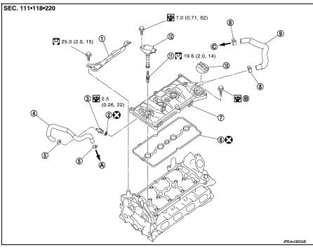
1. Rocker cover protector
2. O-ring
3. PCV control valve
4. PCV hose
5. Clamp
6. Rocker cover gasket
7. Rocker cover
8. Clamp
9. PCV hose
10. Oil filler cap
11. Spark plug
12. Ignition coil
A. To air duct assembly B.Tightening must be done following the installation procedure.
Refer to EM-53
C. To turbocharger inlet tube
 : N·m (kg-m, ft-lb)
 : N·m (kg-m, in-lb)
 : Always replace after every
disassembly.
Removal and Installation
REMOVAL
1. Drain engine coolant. Refer to CO-11, "Draining".
2. Remove engine cover. Refer to EM-25, "Exploded View".
3. Remove intake manifold. Refer to EM-28, "Exploded View".
4. Remove air inlet tube assembly. Refer to EM-31, "Exploded View".
5. Remove PCV hose.
6. Remove rocker cover protector.
7. Disconnect ignition coil harness connector, and them remove ignition coil.
CAUTION:
• Never drop or shock ignition coil.
• Never disassemble ignition coil.
8. Move ignition harness.
9. Remove rocker cover.
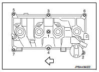
• Loosen bolts in reverse order shown in the figure.
 : Engine front
10. Remove PCV valve and PCV hose, if necessary.
11. Remove rocker cover gasket from rocker cover.
INSTALLATION
1. Install the rocker cover gasket to rocker cover.
CAUTION:
Check the gasket is not dropped.
2. Install rocker cover.
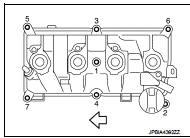
• Tighten bolts in two steps separately in numerical order as shown in the figure.
: Engine front
1st step : 1.96 N·m (0.20 kg-m,
17 in-lb)
2nd step : 8.33 N·m (0.85 kg-m, 74
in-lb)
3. Install in the reverse order of removal, for the rest of parts.
 Fuel injector and fuel tube
Exploded View
1. Holder
2. Seal ring (white)
3. Backup ring
4. O-ring (blue)
5. Fuel injector
6. Stud bolt
7. Fuel tube assembly
8. Fuel tube insulator
9. Fuel tube protector
10. Fu ...
 Unit removal and installation
Engine assembly
2WD
2WD : Exploded View
1. Washer
2. Upper torque rod (RH)
3. Engine mounting insulator (RH)
4. Rear torque rod bracket
5. Rear torque rod
6. Engine mounting insulator (L ...
Other materials:
Operation inspection
Work Procedure
The purpose of the operational check is to check that the individual system
operates normally.
Check condition : Engine running at normal operating temperature.
1.CHECK BLOWER MOTOR
1. Operate fan control dial.
2. Check that fan speed changes. Check operation for all fan speeds ...
P1831 VDC operation signal
DTC Logic
DTC DETECTION LOGIC
DTC CONFIRMATION PROCEDURE
1.DTC REPRODUCTION PROCEDURE
With CONSULT-III
1. Start the engine and drive at 30 km/h (19 MPH) or more.
2. Perform self-diagnosis for “ALL MODE AWD/4WD”.
Is DTC “P1831” detected?
YES >> Proceed to diagnosis procedure ...
Spark plug
Removal and Installation
REMOVAL
1. Remove ignition coil. Refer to EM-178, "Exploded View".
2. Remove spark plug with a spark plug wrench (commercial service
tool).
a : 14 mm (0.55 in)
CAUTION:
Never drop or shock spark plug.
INSTALLATION
Install in the reverse order of removal ...
