Nissan Juke Service and Repair Manual : Unit removal and installation
Engine assembly
2WD
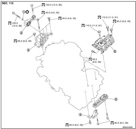
2WD : Exploded View
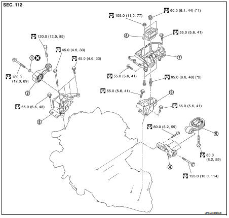
1. Washer
2. Upper torque rod (RH)
3. Engine mounting insulator (RH)
4. Rear torque rod bracket
5. Rear torque rod
6. Engine mounting insulator (LH)
7. Engine mounting frame support (LH)
8. Engine mounting bracket (LH)
 : N┬Ěm (kg-m, ft-lb)
 : Always replace after every
disassembly.
CAUTION:
Check that the stud bolt (*2) is tight at the specified torque before tightening
the mounting nut (*1)
shown in the figure. [Stud bolt (*2) may be loosened after loosening the
mounting nut (*1)]
2WD : Removal and Installation
WARNING:
ÔÇó Situate the vehicle on a flat and solid surface.
ÔÇó Place chocks at front and back of rear wheels.
ÔÇó Attach proper slingers and bolts described in PARTS CATALOG if engine slingers are not equipped.
CAUTION:
ÔÇó Always be careful to work safely, avoid forceful or uninstructed operations.
ÔÇó Never start working until exhaust system and coolant are cool enough.
ÔÇó If items or work required are not covered by the engine section, refer to the applicable sections.
ÔÇó Always use the support point specified for lifting.
ÔÇó Use either 2-pole lift type or separate type lift as best you can. If board-on type is used for unavoidable reasons, support at the rear axle jacking point with a transmission jack or similar tool before starting work, in preparation for the backward shift of center of gravity.
ÔÇó For supporting points for lifting and jacking point at rear axle, refer to GI-36, "Garage Jack and Safety Stand and 2-Pole Lift".
REMOVAL
Outline
Remove the engine and the transaxle assembly from the vehicle downward. Separate
the engine and the transaxle.
Preparation
1. Release fuel pressure. Refer to EC-140, "Work Procedure".
2. Drain engine coolant from radiator. Refer to CO-11, "Draining".
CAUTION:
ÔÇó Perform this step when the engine is cold.
ÔÇó Never spill engine coolant on drive belts.
3. Remove the following parts.
ÔÇó Engine undercover
ÔÇó Front road wheels and tires
ÔÇó Front fender protector (RH and LH): Refer to EXT-22, "Exploded View".
ÔÇó Drive belt: Refer to EM-20, "Removal and Installation".
ÔÇó Engine cover: Refer to EM-25, "Exploded View".
ÔÇó Battery and battery tray: Refer to PG-124, "Exploded View".
ÔÇó Air duct, and air cleaner case assembly and air cleaner body assembly: Refer to EM-26, "Exploded View".
ÔÇó Radiator hose (upper and lower): Refer to CO-17, "Exploded View".
ÔÇó Exhaust front tube: Refer to EX-5, "Exploded View".
ÔÇó Radiator cooling fan assembly: Refer to CO-20, "Exploded View".
ÔÇó Charger air cooler: Refer to EM-31, "Exploded View".
ÔÇó Alternator: Refer to CHG-30, "MR16DDT : Exploded View".
Engine Room LH
1. Disconnect all connections of engine harness around the battery, and then
temporarily secure the engine
harness into the engine side.
CAUTION:
Protect connectors using a resin bag against foreign materials during the
operation.
2. Disconnect fuel feed hose quick connector. Refer to EM-43, "Exploded View".
3. Disconnect heater hoses. Refer to CO-26, "Exploded View".
4. Disconnect control linkage from transaxle. Refer to TM-78, "Exploded View".
5. Remove EVAP hoses. Refer to EM-28, "Exploded View".
6. Disconnect clutch tube on transaxle side from clutch damper. Refer to CL-24, "Exploded View".
Engine Room RH
1. Disconnect vacuum hose from intake manifold. Refer to EM-28, "Exploded
View".
2. Remove A/C compressor. Refer to HA-86, "Exploded View".
3. Remove ground cable at engine side.
Vehicle Underbody
1. Remove ground cable at transaxle side.
2. Remove drive shafts (RH and LH). Refer to FAX-21, "Exploded View".
3. Remove rear torque rod.
4. Remove stabilizer connecting rod. Refer to FSU-16, "Exploded View".
5. Remove front suspension member. Refer to FSU-18, "Exploded View".
6. Preparation for the separation work of transaxle is as follows:
ÔÇó Remove transaxle joint bolts which pierce at oil pan (upper) lower rear side. Refer to EM-99, "Exploded View".
Removal
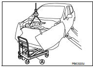
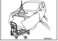
1. Use a manual lift table caddy (commercial service tool) (A) or
equivalently rigid tool such as a transmission jack. Securely support
bottom of the engine and the transaxle assembly.
CAUTION:
Put a piece of wood or an equivalent as the supporting surface,
secure a completely stable condition.
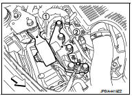
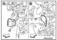
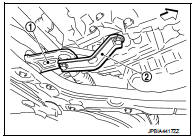
2. Remove upper torque rod (1), and engine mounting insulator (RH) (2).
 : Vehicle front
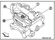
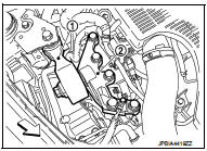
3. Remove engine mounting bracket (LH) through bolt-securing nut (B).
1 : Engine mounting insulator (LH)
2 : Engine mounting bracket support (LH)
A : Through not
: Vehicle front
4. Carefully lower jack, or raise lift to remove the engine and the transaxle assembly. When performing work, observe the following caution.
CAUTION:
ÔÇó Check that no part interferes with the vehicle side.
ÔÇó Before and during this lifting, always check if any harnesses are left connected.
ÔÇó During the removal, always be careful to prevent the vehicle from falling off the lift due to changes in the center of gravity.
ÔÇó If necessary, support the vehicle by setting jack or suitable tool at the rear.
Separation
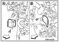
1. Install engine slinger to front cover front left side (A) and cylinder head rear right side (B).
: Engine front
Slinger bolts
Front cover front left
side:  : 32.9 N┬Ěm (3.4 kg-m, 24
ft-lb)
Cylinder head rear
right side:  : 25.0 N┬Ěm (2.6 kg-m, 18
ft-lb)
2. Remove starter motor. Refer to STR-27, "MR16DDT : Exploded View".
3. Lift with a hoist and separate the engine from the transaxle assembly. Refer to TM-84, "MR16DDT : Exploded View".
INSTALLATION
Note the following, and install in the reverse order of removal.
CAUTION:
ÔÇó Never allow engine oil to get on engine mounting insulator. Be careful not to
damage engine mounting
insulator.
ÔÇó Check that each mounting insulator is seated properly, and tighten mounting nuts and bolts.
ÔÇó When installation directions are specified, install parts according to the direction marks on them referring to the figure of components. Refer to EM-55, "2WD : Exploded View".
Rear torque rod bracket 1. Temporarily tighten mounting bolts in the numerical order as shown in the figure.
: Engine front
2. Tighten mounting bolts to the specified torque in the numerical order as shown in the figure.
2WD : Inspection
INSPECTION AFTER INSTALLATION
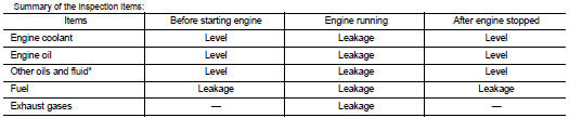
Inspection for Leakage The following are procedures for checking fluids leakage, lubricates leakage, and exhaust gases leakage.
ÔÇó Before starting engine, check oil/fluid levels including engine coolant and engine oil. If less than required quantity, fill to the specified level. Refer to MA-13, "Fluids and Lubricants".
ÔÇó Use procedure below to check for fuel leakage.
- Turn ignition switch ÔÇťONÔÇŁ (with engine stopped). With fuel pressure applied to fuel piping, check for fuel leakage at connection points.
- Start engine. With engine speed increased, check again for fuel leakage at connection points.
ÔÇó Run engine to check for unusual noise and vibration.
ÔÇó Warm up engine thoroughly to check there is no leakage of fuel, exhaust gases, or any oil/fluids including engine oil and engine coolant.
ÔÇó Bleed air from lines and hoses of applicable lines, such as in cooling system.
ÔÇó After cooling down engine, again check oil/fluid levels including engine oil and engine coolant. Refill to the specified level, if necessary.

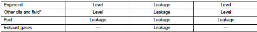
*: Transmission/transaxle/CVT fluid, power steering fluid, brake fluid, etc.
4WD
4WD : Exploded View
1. Washer
2. Upper torque rod (RH)
3. Engine mounting insulator (RH)
4. Rear engine mounting bracket
5. Rear torque rod
6. Engine mounting insulator (LH)
 : N┬Ěm (kg-m, ft-lb)
 : Always replace after every
disassembly.
4WD : Removal and Installation
WARNING:
ÔÇó Situate the vehicle on a flat and solid surface.
ÔÇó Place chocks at front and back of rear wheels.
ÔÇó Attach proper slingers and bolts described in PARTS CATALOG if engine slingers are not equipped.
CAUTION:
ÔÇó Always be careful to work safely, avoid forceful or uninstructed operations.
ÔÇó Never start working until exhaust system and coolant are cool enough.
ÔÇó If items or work required are not covered by the engine section, refer to the applicable sections.
ÔÇó Always use the support point specified for lifting.
ÔÇó Use either 2-pole lift type or separate type lift as best you can. If board-on type is used for unavoidable reasons, support at the rear axle jacking point with a transmission jack or similar tool before starting work, in preparation for the backward shift of center of gravity.
ÔÇó For supporting points for lifting and jacking point at rear axle, refer to GI-36, "Garage Jack and Safety Stand and 2-Pole Lift".
REMOVAL
Outline
Remove the engine and the transaxle assembly from the vehicle downward. Separate
the engine and the transaxle.
Preparation
1. Release fuel pressure. Refer to EC-140, "Work Procedure".
2. Drain engine coolant from radiator. Refer to CO-11, "Draining".
CAUTION:
ÔÇó Perform this step when the engine is cold.
ÔÇó Never spill engine coolant on drive belts.
3. Remove the following parts.
ÔÇó Engine undercover
ÔÇó Front road wheels and tires
ÔÇó Front fender protector (RH and LH): Refer to EXT-22, "Exploded View".
ÔÇó Drive belt: Refer to EM-20, "Removal and Installation".
ÔÇó Engine cover: Refer to EM-25, "Exploded View".
ÔÇó Battery and battery tray: Refer to PG-124, "Exploded View".
ÔÇó Air duct, air cleaner case assembly and air cleaner body assembly: Refer to EM-26, "Exploded View".
ÔÇó Radiator hose (upper and lower): Refer to CO-17, "Exploded View".
ÔÇó Radiator cooling fan assembly: Refer toCO-20, "Exploded View".
ÔÇó Exhaust front tube: Refer to EX-5, "Exploded View".
ÔÇó Alternator: Refer to CHG-30, "MR16DDT : Exploded View".
Engine Room LH
1. Disconnect all connections of engine harness around the battery, and then
temporarily secure the engine
harness into the engine side.
CAUTION:
Protect connectors using a resin bag against foreign materials during the
operation.
2. Disconnect fuel feed hose quick connector. Refer to EM-43, "Exploded View".
3. Disconnect heater hoses. Refer to CO-26, "Exploded View".
4. Disconnect control cable from transaxle. Refer to TM-273, "Exploded View".
5. Remove EVAP hoses. Refer to EM-28, "Exploded View".
Engine Room RH
1. Disconnect vacuum hose from intake manifold. Refer to EM-28, "Exploded
View".
2. Remove A/C compressor. Refer to HA-86, "Exploded View".
3. Remove ground cable at engine side.
Vehicle Underbody
1. Remove ground cable at transaxle side.
2. Remove rear propeller shaft. Refer to DLN-121, "Exploded View".
3. Remove drive shafts (RH and LH). Refer to FAX-21, "Exploded View".
4. Remove rear torque rod (1).
2 : Rear engine mounting bracket
 : Vehicle front
5. Remove stabilizer connecting rod. Refer to FSU-16, "Exploded View".
6. Rear front suspension member. Refer to FSU-18, "Exploded View".
7. Preparation for the separation work of transaxle is as follows: ÔÇó Remove transaxle joint bolts which pierce at oil pan (upper) lower rear side. Refer to EM-40, "Exploded View".
Removal
1. Use a manual lift table caddy (commercial service tool) (A) or
equivalently rigid tool such as a transmission jack. Securely support
bottom of the engine and the transaxle assembly.
CAUTION:
Put a piece of wood or an equivalent as the supporting surface,
secure a completely stable condition.
2. Remove upper torque rod (1) and engine mounting insulator (RH) (2).
: Vehicle front
3. Remove engine mounting bracket (LH).
4. Carefully lower jack, or raise lift to remove the engine and the transaxle assembly. When performing work, observe the following caution.
CAUTION:
ÔÇó Check that no part interferes with the vehicle side.
ÔÇó Before and during this lifting, always check if any harnesses are left connected.
ÔÇó During the removal, always be careful to prevent the vehicle from falling off the lift due to changes in the center of gravity.
ÔÇó If necessary, support the vehicle by setting jack or suitable tool at the rear.
Separation
1. Install engine slinger to front cover front left side (A) and cylinder head rear right side (B).
: Engine front
Slinger bolts
Front cover front left
side:  : 32.9 N┬Ěm (3.4 kg-m, 24
ft-lb)
Cylinder head rear
right side:  : 25.0 N┬Ěm (2.6 kg-m, 18
ft-lb)
2. Remove starter motor. Refer to STR-27, "MR16DDT : Exploded View".
3. Lift with a hoist and separate the engine from the transaxle assembly. Refer to TM-301, "Exploded View" (CVT models).
INSTALLATION
Note the following, and install in the reverse order of removal.
CAUTION:
ÔÇó Never allow engine oil to get on engine mounting insulator. Be careful not to
damage engine mounting
insulator.
ÔÇó Check that each mounting insulator is seated properly, and tighten mounting nuts and bolts.
ÔÇó When installation directions are specified, install parts according to the direction marks on them referring to the figure of components. Refer to EM-59, "4WD : Exploded View".
4WD : Inspection
INSPECTION AFTER INSTALLATION
Inspection for Leakage The following are procedures for checking fluids leakage, lubricates leakage, and exhaust gases leakage.
ÔÇó Before starting engine, check oil/fluid levels including engine coolant and engine oil. If less than required quantity, fill to the specified level. Refer to MA-13, "Fluids and Lubricants".
ÔÇó Use procedure below to check for fuel leakage.
- Turn ignition switch ÔÇťONÔÇŁ (with engine stopped). With fuel pressure applied to fuel piping, check for fuel leakage at connection points.
- Start engine. With engine speed increased, check again for fuel leakage at connection points.
ÔÇó Run engine to check for unusual noise and vibration.
ÔÇó Warm up engine thoroughly to check there is no leakage of fuel, exhaust gases, or any oil/fluids including engine oil and engine coolant.
ÔÇó Bleed air from lines and hoses of applicable lines, such as in cooling system.
ÔÇó After cooling down engine, again check oil/fluid levels including engine oil and engine coolant. Refill to the specified level, if necessary.
*: Transmission/transaxle/CVT fluid, power steering fluid, brake fluid, etc.
 Ignition coil, spark plug and rocker cover
Exploded View
1. Rocker cover protector
2. O-ring
3. PCV control valve
4. PCV hose
5. Clamp
6. Rocker cover gasket
7. Rocker cover
8. Clamp
9. PCV hose
10. Oil filler cap
11. Spark ...

Other materials:
P2127, P2128 APP sensor
DTC Logic
DTC DETECTION LOGIC
DTC CONFIRMATION PROCEDURE
1.PRECONDITIONING
If DTC Confirmation Procedure has been previously conducted, always turn
ignition switch OFF and wait at
least 10 seconds before conducting the next test.
TESTING CONDITION:
Before performing the following proced ...
B1089 seat belt Pre-tensioner LH
DTC Logic
DTC DETECTION LOGIC
DTC CONFIRMATION PROCEDURE
1.CHECK SELF-DIAG RESULT
With CONSULT-III
1. Turn ignition switch ON.
2. Perform ÔÇťSelf Diagnostic ResultÔÇŁ mode of ÔÇťAIR BAGÔÇŁ using CONSULT-III.
Without CONSULT-III
1. Turn ignition switch ON.
2. Check the air bag warning la ...
Security indicator lamp does not turn on or blink
Description
Security indicator lamp does not blink when ignition switch is in a position
other than ON.
NOTE:
ÔÇó Before performing the diagnosis, check ÔÇťWork FlowÔÇŁ. Refer to SEC-47, "Work
Flow".
ÔÇó Check that vehicle is under the condition shown in ÔÇťCONDITIONS OF VEHICLE ...
